Insulated wall assembly

a technology of insulating panels and walls, applied in the direction of walls, joists, girders, etc., can solve the problems of limiting the adoption and implementation of insulating panels in the housing market, difficult interconnection of wires and rods, time-consuming construction, etc., and achieve the effect of facilitating wall assembly

Inactive Publication Date: 2007-08-14
EFFICIENT BUILDING SYST L L C
View PDF96 Cites 53 Cited by
  • Summary
  • Abstract
  • Description
  • Claims
  • Application Information

AI Technical Summary

Benefits of technology

[0010]The present invention comprises a concrete wall assembly having features that address the needs of the commercial and residential housing markets. The invention incorporates a concrete form having two panels. Each panel sandwiches a frame of studs to define concrete receiving cavities between the first panel and the second panel and the studs. Applicant has discovered by pouring concrete into vertically erected receiving cavities at a job site, the cost of employing its inventive wall assembly is greatly reduced. Accordingly, many of its inventive features facilitate construction in this manner.
[0011]For example, in contrast to existing wall assemblies, the inventive wall panel assembly has a vertically oriented fastening strip that attaches at least one of the panels to the frame. The fastening strip may attach the panel to a stud of the frame. Insulating panels as well as cementitious panels may be used with the inventive assembly. By orienting the fastening strip vertically, the inventive wall assembly prevents concrete from seeping between the panel and the stud when the concrete is poured into a vertically erected wall assembly.
[0012]In addition, the inventive concrete wall assembly has an opening at the bottom that permits concrete to pour vertically from the frame to a concrete footing. Unlike existing assemblies, this opening extends from panel to panel and allows the concrete in the wall assembly to cure on the footing without any intervening plate to degrade the connection between the concrete wall and the concrete footing. To further improve this connection, a groove may be provided in the concrete footing to create a form for a keyway for the vertically poured concrete. A reinforcing member, such as a metal rod, may be embedded in both the concrete wall and the concrete footing to strengthen this connection between the concrete wall and the concrete footing.
[0015]Another important feature for the commercialization of the inventive wall assembly includes the incorporation of a port, such as a window or door, as part of the wall assembly. The studs are vertically erected and spaced apart to form a port. The studs are then sandwiched by a first panel and a second panel to form a first concrete receiving cavity forming one side of the port and a second concrete receiving cavity forming a second side of the port. In contrast to existing designs, the inventive wall assembly has cavities open to receive concrete along the vertical direction of the studs. The concrete is poured into the first concrete receiving cavity and the second concrete receiving cavity. By pouring concrete to form the door or window along the vertical direction of the studs, the inventive wall assembly allows the window or door to be formed following erection of the wall assembly at the construction site, thereby reducing construction costs.
[0019]The truss anchor may be a hook. The hook has an opening to receive the reinforcing member. The opening may be expandable between a first dimension and a second dimension. The first dimension is greater than a dimension of the reinforcing member and the second dimension is less than the dimension of the reinforcing member. This feature permits the hook to be quickly attached around the reinforcing member to facilitate assembly of the wall to a roof truss. The truss anchor may then be embedded in concrete to further strengthen the connection between the wall and the roof.

Problems solved by technology

However, stacked courses of blocks are time-consuming to construct.
However, the interconnecting wires and rods are difficult and time consuming to assemble with insulating panels.
The foregoing designs each have drawbacks that limit their adoption and implementation into the housing market.
These wall assemblies lack certain features that permit their ready incorporation into large scale housing projects and are relatively very expensive to produce and construct.
Consequently, their use has been limited to the upper spectrum of the housing market.

Method used


Image

  • Insulated wall assembly
  • Insulated wall assembly
  • Insulated wall assembly

Examples


Embodiment Construction

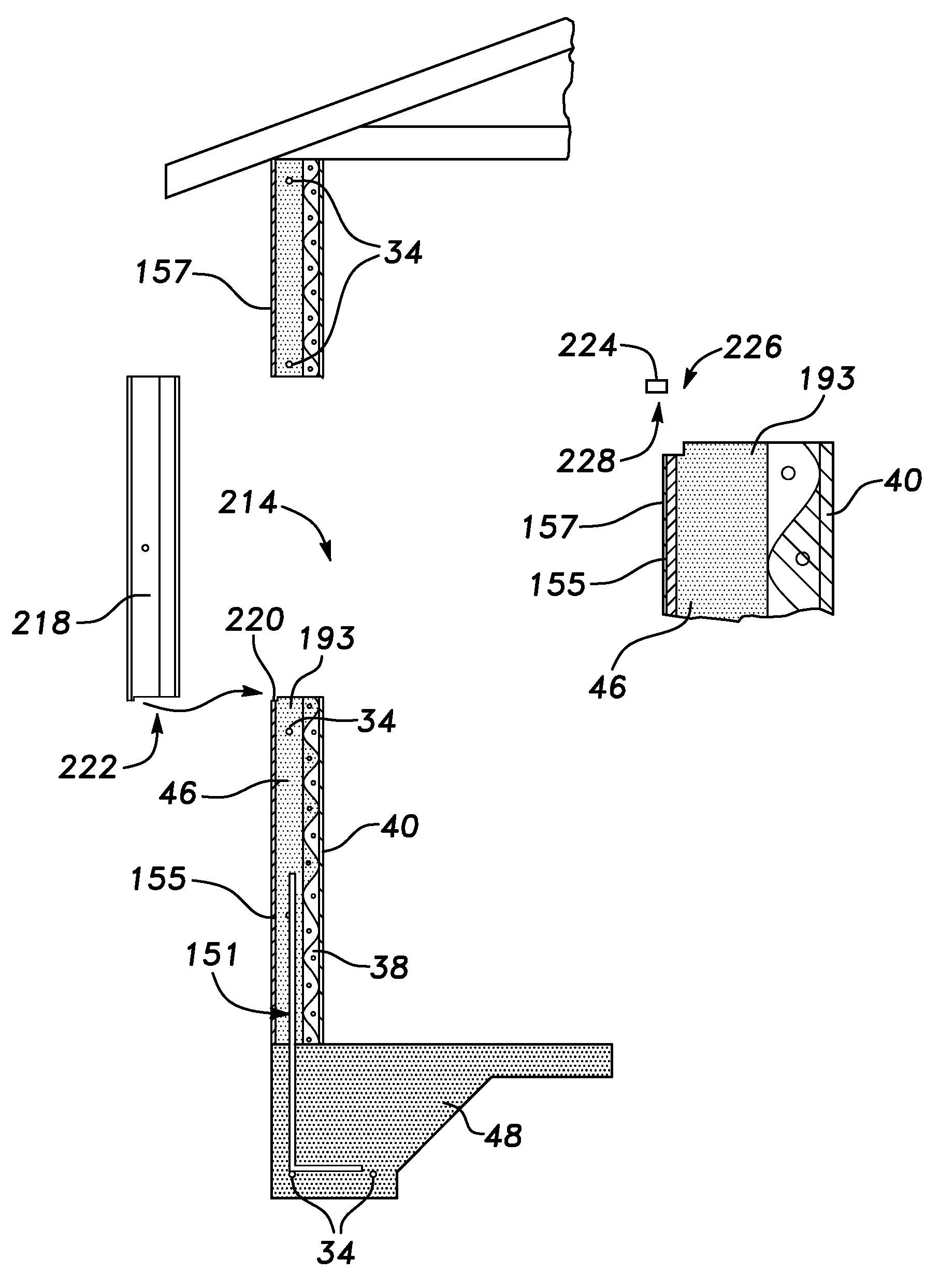
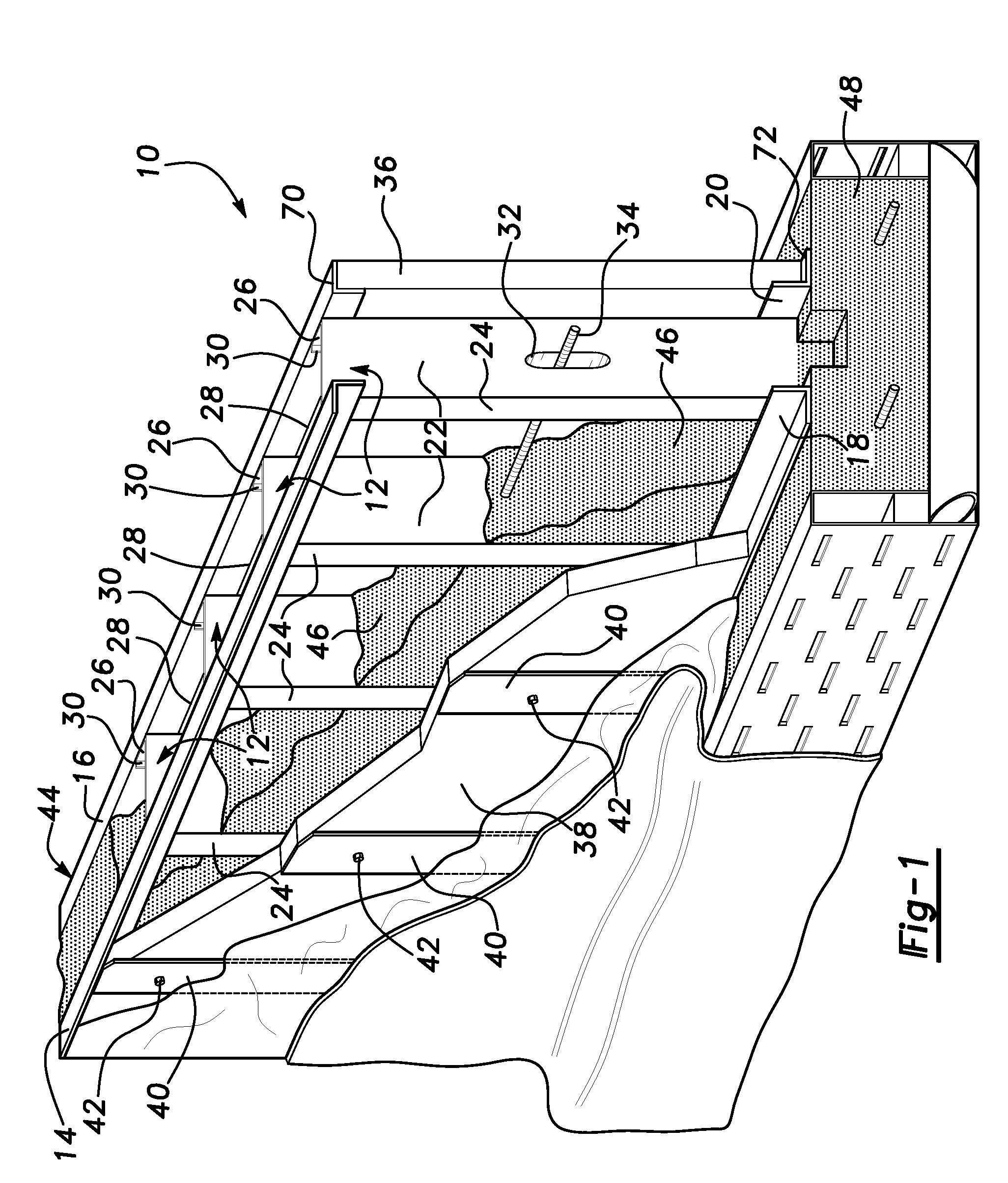
[0040]An insulated concrete 46 wall construction assembly constructed according to this invention is shown at 10 in the drawings. The assembly 10 includes a series of 18 gauge steel studs 12 oriented vertically and parallel to one another spaced approximately ten inches apart on center. The studs 12 are held in place relative to one another by 20 gauge steel angle strip cross members 14, 16, 18, 20 to form a frame or framework 21. Two top angle strips 14, 16 are fastened across the studs 12 at opposite sides of upper ends of studs 12 and two bottom angle strips 18, 20 are fastened across the studs 12 at opposite side of respective bottom ends of the stud 12.

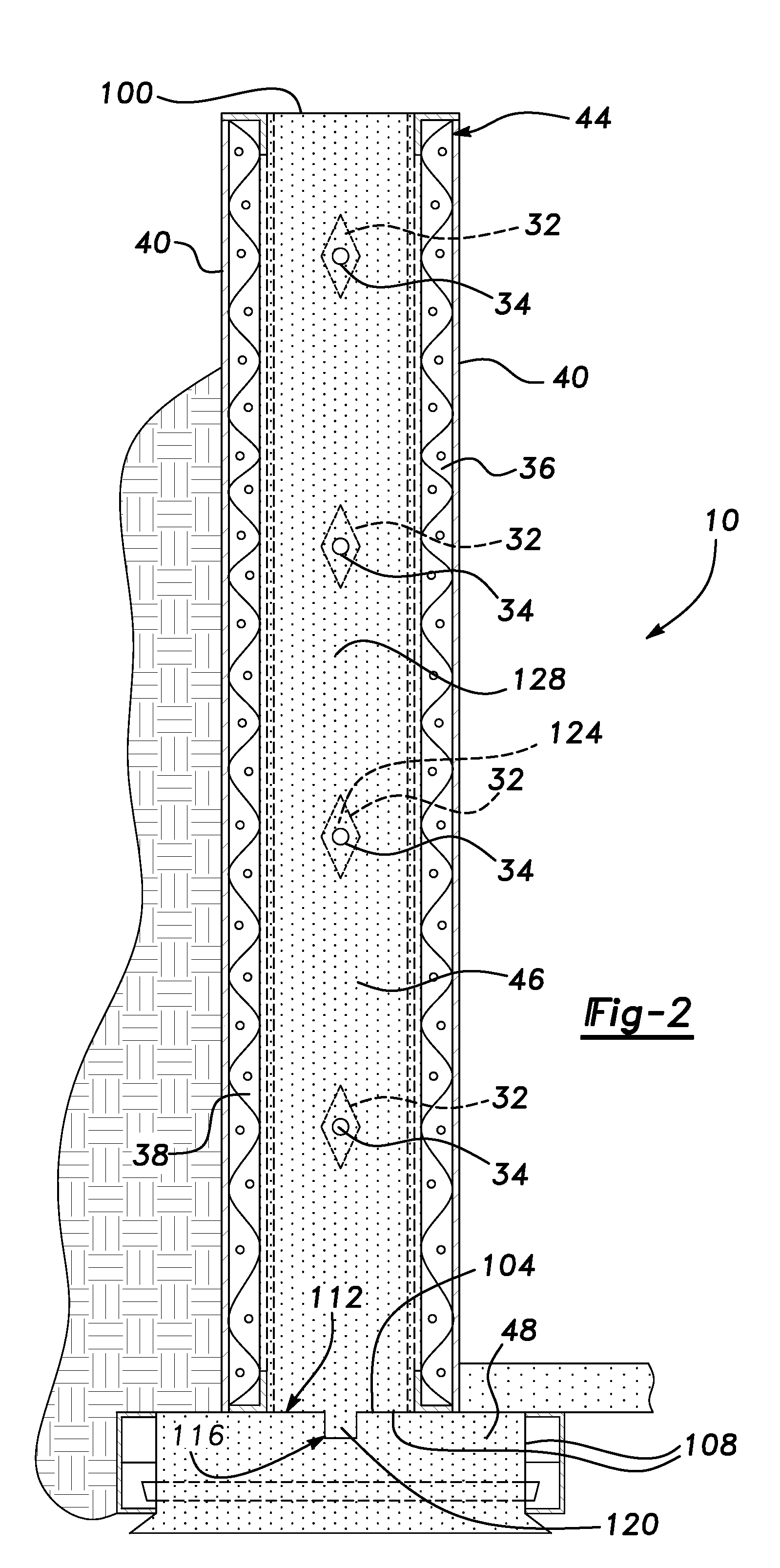
[0041]The studs 12 are of standard construction well known in the art and are formed from rolled steel. As best shown in FIG. 2, each stud 12 has a C-shaped cross-section and is formed to include an elongated main panel 22 and a pair of opposing flanges 24, 26 that extend integrally and perpendicularly from along the length of ma...


PUM


Abstract

A concrete form panel has a plurality of studs. A first and second panel are fastened to the studs to define concrete receiving cavities between the first panel and the second panel. A fastening strip attaches the panels to the stud and is vertically oriented. In addition, a netting may span the studs. An opening extending from panel to panel may create a concrete-to-concrete interface between concrete in the form panel and a concrete footing. A column may be formed in this fashion. Moreover, ports, such as windows and door, may be provided in wall assembly. The assembly may be attached by a truss anchor to a truss for a roof.

Description

CROSS REFERENCE TO RELATED APPLICATIONS[0001]This application is a continuation-in-part of U.S. Non-Provisional Patent Application Ser. No. 09 / 795,662 filed Feb. 28, 2001 now U.S. Pat. No. 6,622,452, which claims priority to U.S. Provisional Patent Application U.S. Ser. No. 60 / 229,068, filed Aug. 30, 2000 and is a continuation-in-part of U.S. Non-Provisional Patent Application Ser. No. 09 / 246,977, filed Feb. 9, 1999 now abandoned.BACKGROUND OF THE INVENTION[0002]This invention relates to an insulated concrete wall assembly.[0003]Insulating concrete form (ICF) systems are known for use in constructing exterior wall systems with high performance and environmentally friendly materials that have vastly improved the energy efficiency, air quality, durability and overall comfort of dwelling structures. One example of such a system is disclosed in U.S. Pat. No. 4,223,501 issued Sep. 23, 1980 to DeLozier (the DeLozier patent). The DeLozier patent discloses an insulated concrete wall form co...

Claims


Application Information

Patent Timeline
Patent Type & Authority Patents(United States)
IPC IPC(8): E04B2/40E04B2/86E02D27/02E04B1/00E04B2/56E04C3/04E04C3/09E04C3/34E04C5/06
CPCE02D27/02E04B1/0007E04B1/161E04B2/8647E04B7/04E04B7/045E04C3/09E04C3/34E04C5/06E04B2/8658E04B2002/565E04C2003/0421E04C2003/0434E04C2003/046E04C2003/0473
Inventor STEFANUTTI, OSCARALVARO, TIMOTHYSTEFANUTTI, PAULWILLWERTH, JOHN
Owner EFFICIENT BUILDING SYST L L C
Why Eureka
Try Eureka