Method and device for realizing an electrical bicycle lock

Inactive Publication Date: 2014-12-04
ROBERT BOSCH GMBH
View PDF2 Cites 7 Cited by
  • Summary
  • Abstract
  • Description
  • Claims
  • Application Information

AI Technical Summary

Benefits of technology

[0009]In one development of the present invention, the locking device has an electrically controllable and thus activatable operating device, which is realized by a motor, a spindle, a spring or a magnet, for example. This actuating device makes it possible to move the blocking element in order to lock and/or open the locking device.
[0010]In one special further development of the invention, if an obstacle, especially a spoke, is detected in the path of the blocking element to the closing position, a drive unit installed on the bicycle rotates the wheel of the bicycle in such a way that locking becomes possible. Such drive units, for example,

Problems solved by technology

However, when a permanently installed bicycle lock is used for the locking, a situation may arise in which the locking element hits a spoke and the locking process is blocked as a re

Method used


Image

  • Method and device for realizing an electrical bicycle lock
  • Method and device for realizing an electrical bicycle lock

Examples


Embodiment Construction

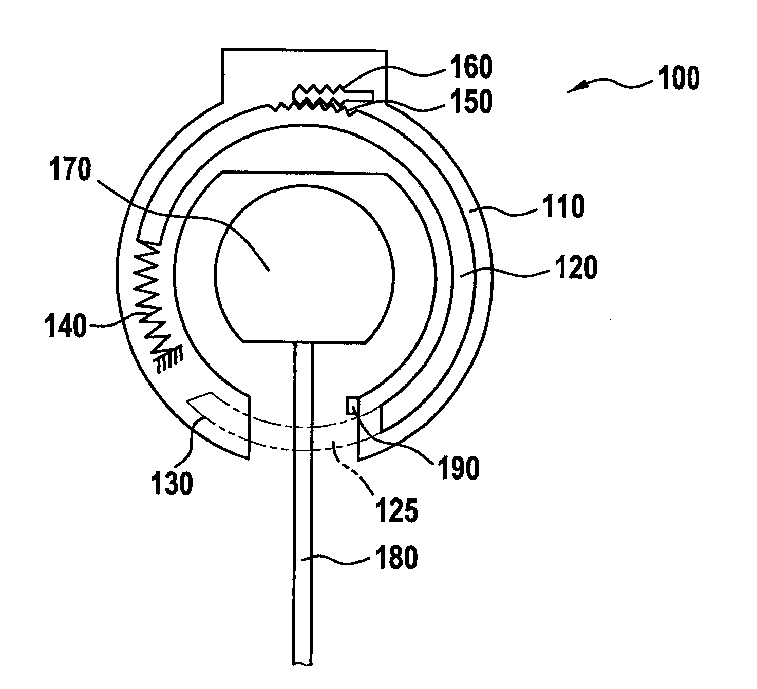
[0014]In general, the present invention is able to be used in a multitude of different designs of (bicycle) locks, in which a movable blocking element is employed to block a wheel of a bicycle. According to FIG. 1, the present invention is illustrated on the basis of a frame lock, but other bicycle locks, especially locks that are not permanently installed on the bicycle, may be equipped with the invention as well.

[0015]As shown in FIG. 1, a typical locking device as illustrated in the form of a frame lock 100 is situated around a tire 170 of a wheel. A movable blocking element or a locking bar 120, which is rotationally mounted in the exemplary embodiment at hand, is provided in housing 110 of frame lock 100. In the locked state of frame lock 100, this locking bar 120 is rotated into position 125 and inserted or snapped into place in a corresponding opposite lying receptacle 130 of housing 110. Housing 110 and locking bar 125 completely enclose tire 170 in the closed state, so that...


PUM


Abstract

A device and a method for theft protection of a bicycle are described, as well as a bicycle equipped with such a device or such a method. A control unit is provided, with the aid of which a locking device is able to be electrically activated in order to block at least the rotation of one wheel of a bicycle. Furthermore, a detection unit is provided, which additionally detects to what extent blocking of the wheel by the locking device is able to take place to begin with. The locking device is electrically activated, i.e., operated, only if blocking of the wheel, e.g., by means of a movable blocking element of the locking device, is actually also possible.

Description

FIELD OF THE INVENTION[0001]The present invention relates to a method and an anti-theft device for a bicycle, and it also relates to a bicycle which is equipped with such a method or a corresponding device.BACKGROUND INFORMATION[0002]Various types of vehicle locks for securing bicycles from theft are known already. For example, in addition to bicycle locks that can be mounted on the bicycle frame retroactively with the aid of a corresponding mount, permanently installed locks are used as well. While separate bicycle locks have the advantage of being usable individually, for example by chaining them to a stationary object, permanently installed locks allow rapid handling.[0003]When using an electric bicycle, it is furthermore also possible to utilize the electrification of the bicycle as theft protection. For example, German Published Patent Appln. No. 10 2005 041 269 describes a locking device in the form of a frame lock provided with a movable locking bar, which is able to be elect...

Claims


Application Information

Patent Timeline
IPC IPC(8): E05B71/00
CPCE05B71/00B62H5/14B62H5/147Y10T70/402
Inventor DASBACH, GREGOR
Owner ROBERT BOSCH GMBH
Why Eureka
Try Eureka