Method and apparatus for loading and implanting a shape memory implant

US20140358187A1Active Publication Date: 2014-12-04BIOMEDICAL ENTERPRISES

Image

  • Method and apparatus for loading and implanting a shape memory implant
  • Method and apparatus for loading and implanting a shape memory implant
  • Method and apparatus for loading and implanting a shape memory implant

Examples


first embodiment

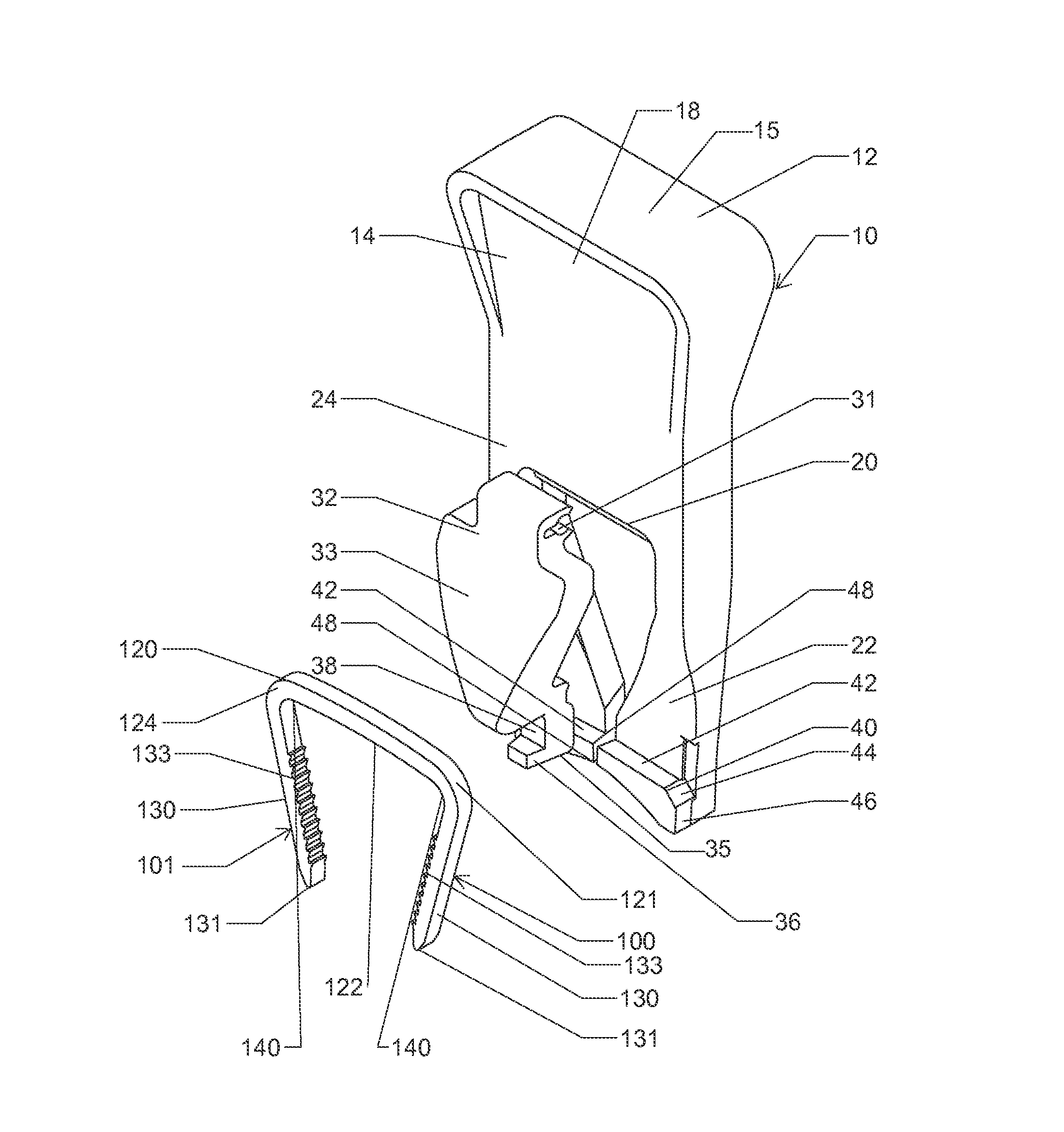
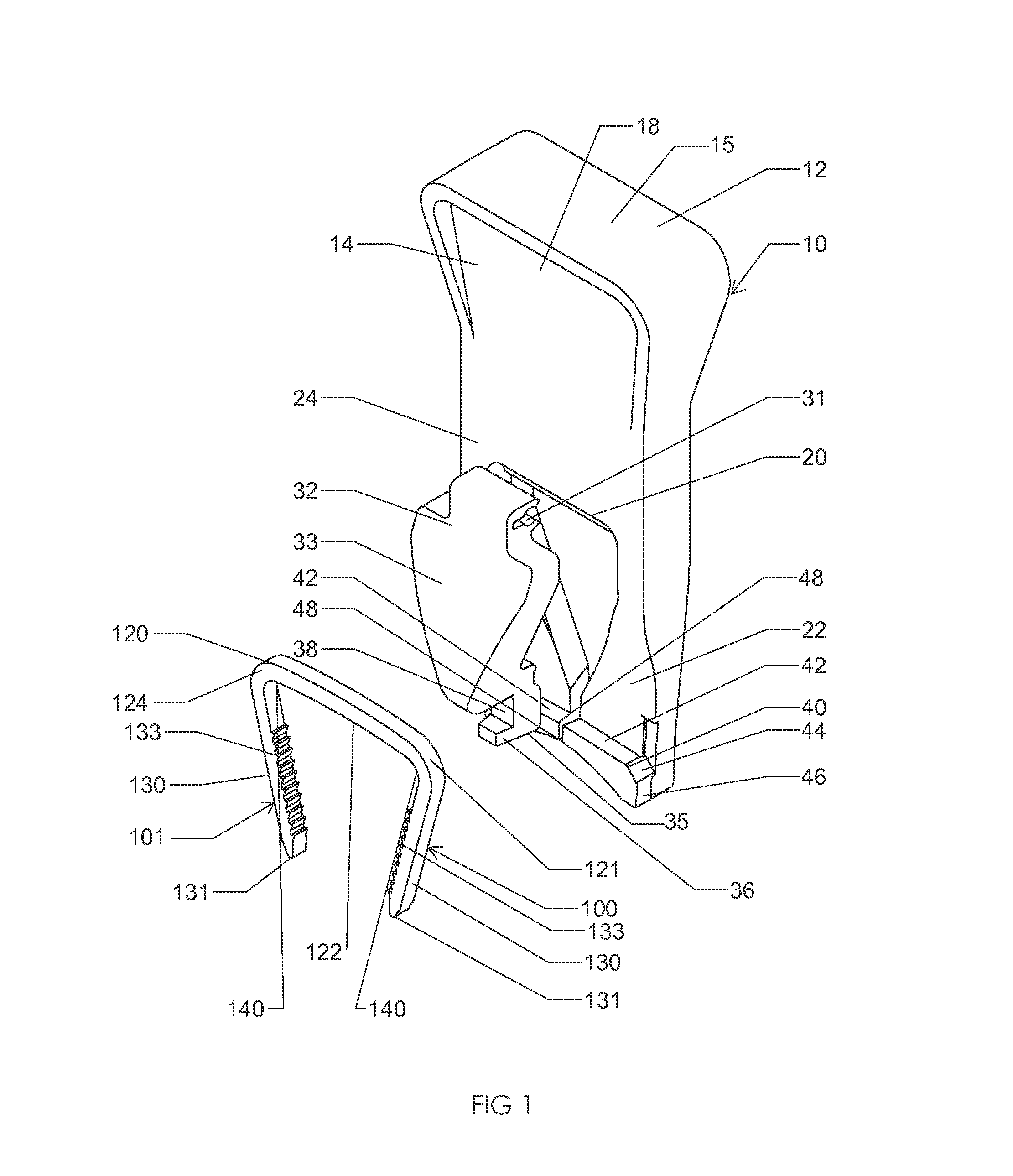
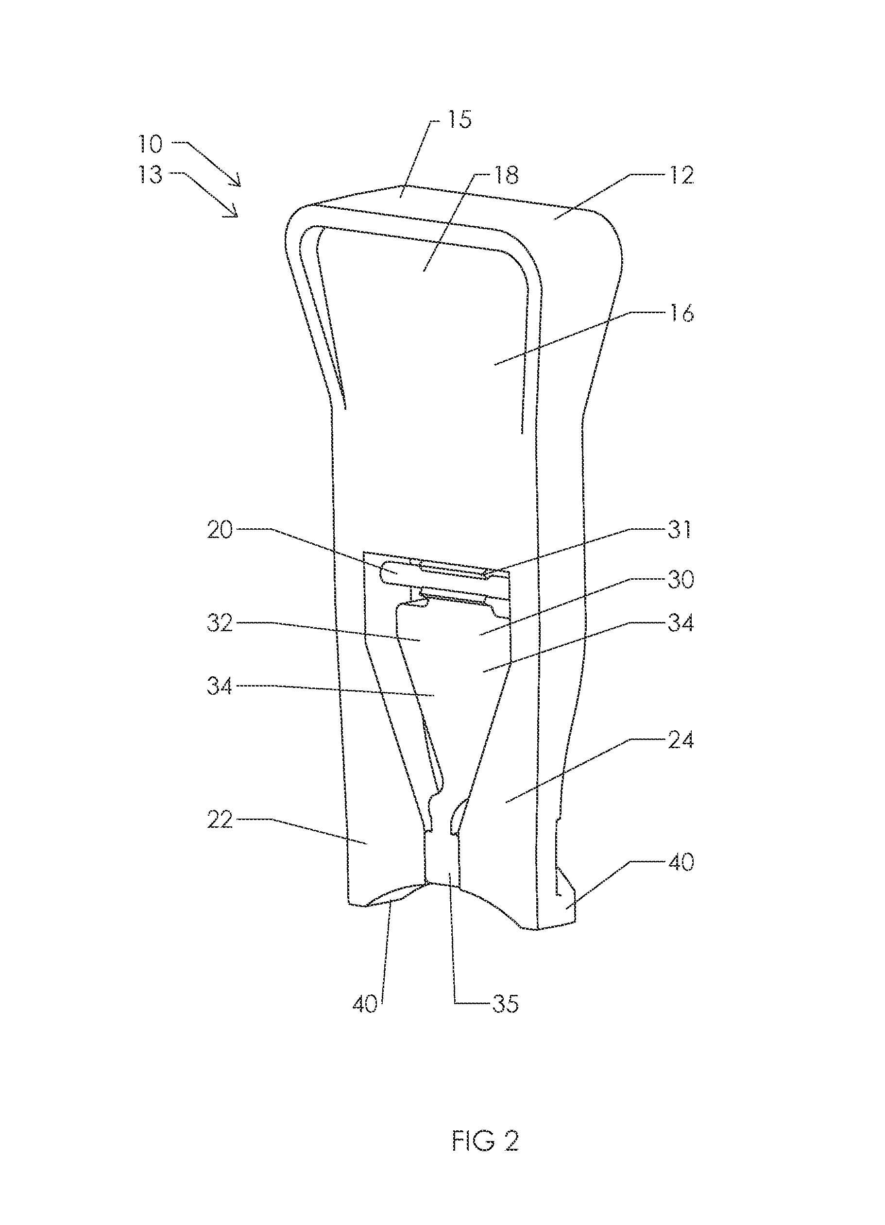
[0068]FIGS. 1 and 2 are an illustration of an implant insertion device 10 and an implant 100. The implant 100 secures to the implant insertion device 10 allowing a surgeon to insert the implant 100 into tissue or bone during surgery.

[0069]In the first embodiment, the implant 100 is a surgical staple and includes a bridge 120 and legs 130 formed integrally at corners 140. The bridge further 120 includes a top 121, a bottom 122, a back 123, and a front 124. The legs 130 further include tips 131 and bone retention notches 133. The tips 131 of the legs 130 may form a shape that is rounded for insertion into drill holes or the tips 131 may be pointed for impaction into bones. The retention notches 133 are designed to grip tissue or bone and prevent slippage once the implant 100 has been inserted into tissue or bone. While the first embodiment discloses the implant 100 as a surgical staple, it should be understood by one of ordinary skill in the art that any implant such as a staple or pl...

second embodiment

[0089]FIGS. 20-31 are an illustration of an implant insertion device 50 and an implant 200. The implant 200 is secured to the implant insertion device 50 allowing a surgeon to insert the implant 200 into tissue or bone during surgery.

[0090]In the second embodiment, the implant 200 is a surgical staple and includes two bridges 210 and 211 and legs 220 formed integrally at corners 230. The bridges 210 and 211 each include a top 212, a bottom 213, a back 214, and a front 215. The legs 220 further include tips 221 and bone retention notches 223. The tips 221 of the legs 220 may form a shape that is rounded for insertion into drill holes or the tips 221 may be pointed for impaction into bones. The retention notches 223 are designed to grip tissue or bone and prevent slippage once the implant 200 has been inserted into tissue or bone. While the second embodiment discloses the implant 200 as a surgical staple, it should be understood by one of ordinary skill in the art that any implant ada...


PUM

PropertyMeasurementUnit
Temperatureaaaaaaaaaa
Lengthaaaaaaaaaa
Speedaaaaaaaaaa

Abstract

An implant insertion system includes a shape memory implant movable between a first shape a second shape and an implant insertion device movable between an implant disengagement position and an implant engagement position. The implant insertion device receives the shape memory implant in its first shape while in its implant disengagement position. Movement of the implant insertion device from its implant disengagement position to its implant engagement position manipulates the shape memory implant from its first shape to its second shape. The implant insertion device maintains the shape memory implant in its second shape until delivery of the shape memory implant into tissue or bone.

Description

BACKGROUND OF THE INVENTION[0001]1. Field of the Invention[0002]The present invention relates generally to an implantation device and, more particularly, but not way of limitation, to an implantation device designed for loading with a surgical implant and for subsequent delivery of the surgical implant. The implantation device uses jaws and a spacer to secure a surgical implant and allow implantation into a patient.[0003]2. Description of the Related Art[0004]Shape memory implants are commonly used in surgical procedures that require the reattachment or fusing of tissue or bone. Shape memory implants can be composed of shape memory material such as Nitinol that allows the shape memory implants to have a first final shape and the ability to transform into a second shape. The shape memory material gives the implants elastic properties in that they store mechanical energy and are subject to elastic (recoverable) deformation when they release the stored mechanical energy. The implants a...

Claims


Application Information

Patent Timeline
04 Dec 2014
Publication
US20140358187A1
IPC
A61B17/88
CPC
A61B2017/564; A61B17/8872; A61B17/0642; A61B17/0682; A61B17/0684; A61B17/10; Y10T29/49826
Inventors
TABER, JOSEPH H.; KNIGHT, ADAM T.