Joint lock

a joint lock and locking bar technology, applied in the field of joint locks, can solve the problem of inability to remove the introduced locking bar from the lock body, and achieve the effect of simple handling

Active Publication Date: 2014-12-11
ABUS AUGUST BREMICKER SOEHNE AG
View PDF50 Cites 5 Cited by
  • Summary
  • Abstract
  • Description
  • Claims
  • Application Information

AI Technical Summary

Benefits of technology

[0006]It is an object of the invention to pr

Problems solved by technology

A removal of the introduced locking bar from the

Method used


Image

  • Joint lock
  • Joint lock
  • Joint lock

Examples


Embodiment Construction

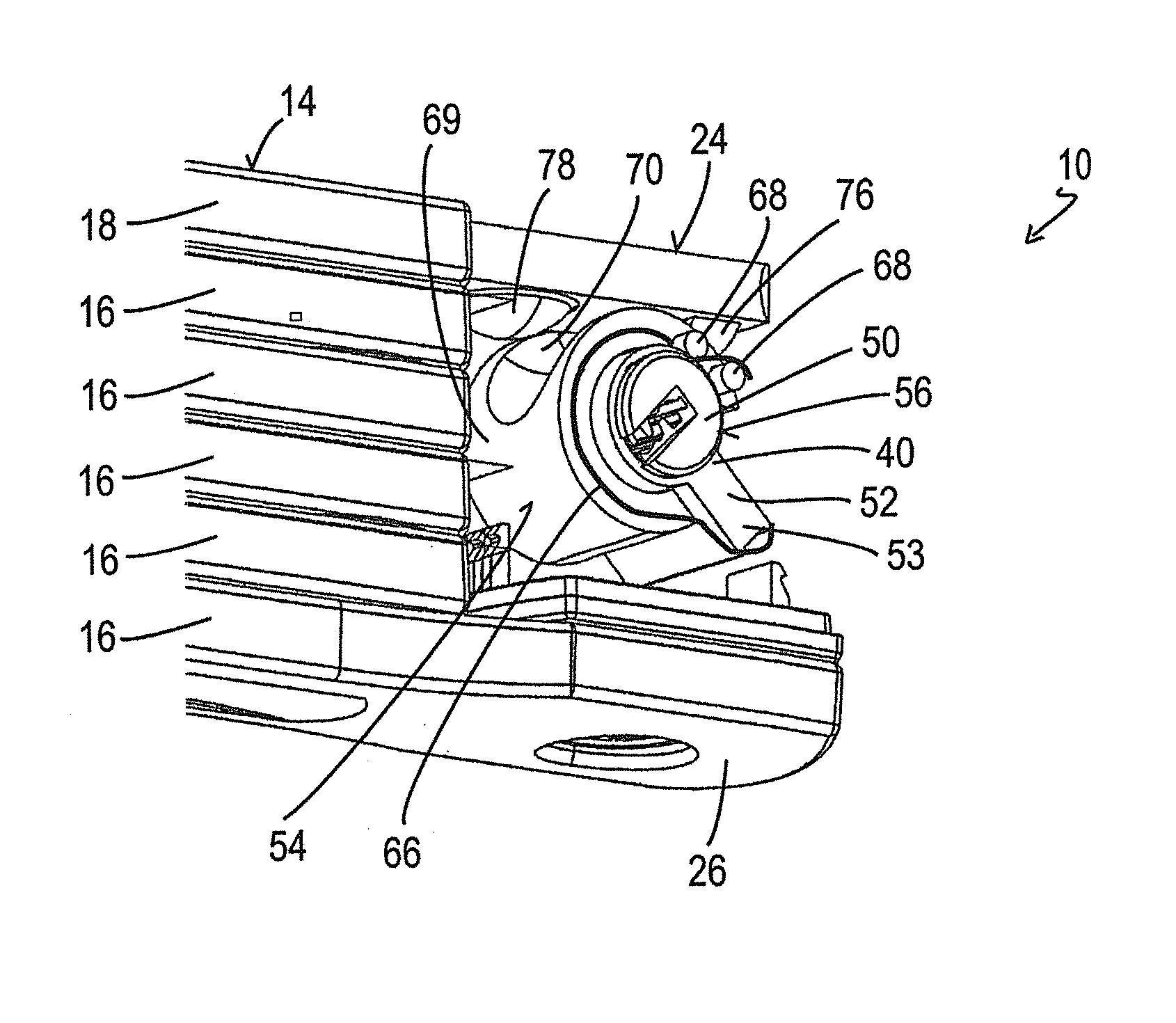
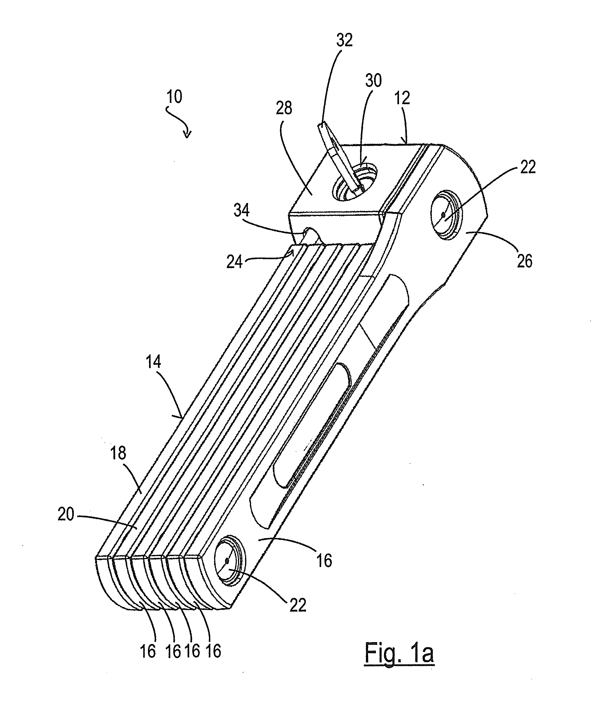
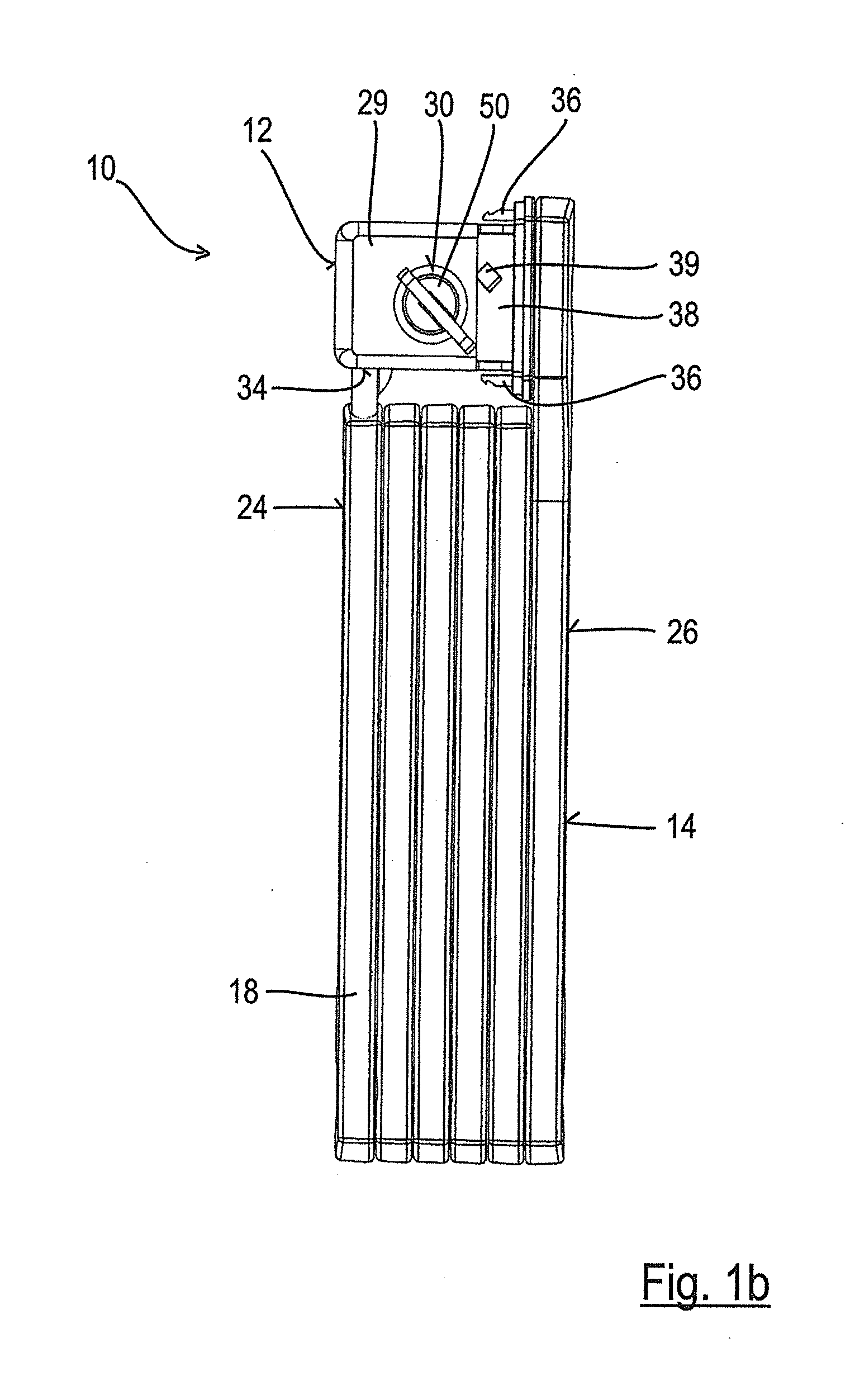
[0039]The joint lock 10 shown in FIG. 1a comprises a lock body 12 as well as a joint bar hoop 14 fastened thereto. The joint bar hoop 14 can be folded together to form a compact unit and can in this state preferably also be locked at the lock body 12. In the unlocked state of the joint lock 10, the joint bar hoop 14 can be folded apart to form a loop in a known manner and hereby to lock a two-wheeler or to secure it to another object (e.g. a bicycle stand).

[0040]The joint bar hoop 14 in detail has a plurality of joint bars 16 of which one is formed as a locking bar 18. The joint bars 16 and the locking bar 18 are each flat and preferably comprise steel which is surrounded by a plastic jacket 20 to avoid damage to the two-wheeler to be locked. The joint bars 16 and the locking bar 18 are pivotally connected to one another in series by a respective rivet 22 such that the joint axes extend in parallel with or coaxial to one another and the joint bar hoop 14 can be folded together in th...


PUM


Abstract

A joint lock comprises a lock body and a joint bar hoop, wherein the lock body accommodates a lock cylinder and a latch which is selectably movable by the lock cylinder from a locked position into a release position and wherein the joint bar hoop comprises a plurality of joint bars pivotally linked to one another, wherein a first end of the joint bar hoop has an elongate closing bar which can be introduced into an introduction opening of the lock body and which can be locked in the lock body by means of the latch. The joint lock is characterized in that the lock body furthermore accommodates a preloading device which preloads the latch into the locking position, with the latch being temporarily movable against the preloading from the locking position into the release position by introduction of the locking bar into the lock body, with the preloading device being adapted to move the latch back into the locking position again when the locking bar is completely introduced into the lock body.

Description

CROSS-REFERENCE TO RELATED APPLICATIONS[0001]This application claims priority of German Patent Application 102013210475.8 filed on Jun. 5, 2013.FIELD OF THE INVENTION[0002]The present invention relates to a joint lock having a lock body and a joint bar hoop, wherein the lock body accommodates a lock cylinder and a latch which is selectably movable by the lock cylinder from a locked position into a release position and wherein the joint bar hoop comprises a plurality of joint bars pivotally connected to one another, wherein a first end of the joint bar hoop has an elongate locking bar which can be introduced into an introduction opening of the lock body and which can be locked in the lock body by means of the latch.BACKGROUND OF THE INVENTION[0003]Such a joint lock serves, for example, for the securing of a two-wheeler to a bicycle stand, to a lamppost or the like. For this purpose, the joint bars of the joint bar hoop which are pivotally connected to one another behind one another o...

Claims


Application Information

Patent Timeline
IPC IPC(8): E05B67/00
CPCE05B67/003E05B71/00Y10T70/409E05B73/00E05B73/0005
Inventor MULLER, THOMASHOMMEL, MARTIN
Owner ABUS AUGUST BREMICKER SOEHNE AG
Why Eureka
Try Eureka