Brushless permanent-magnet motor

a permanent magnet, brushless technology, applied in the direction of dynamo-electric machines, magnetic circuit rotating parts, magnetic circuit shapes/forms/construction, etc., can solve the problems of lowering the motor performance, affecting the normal functioning of the brushless permanent magnet motor after a long time, and becoming more serious, so as to solve vibration and noise problems, reduce the effect of air gap flux density variation, instant cogging torque and torque ripples, and high structural stability

Inactive Publication Date: 2014-12-11
DURQ MACHINERY
View PDF9 Cites 3 Cited by
  • Summary
  • Abstract
  • Description
  • Claims
  • Application Information

AI Technical Summary

Benefits of technology

[0008]The present invention has been accomplished under the circumstances in view. It is the main object of the present invention to provide a brushless permanent-magnet motor, which has a high level of structural stability, and can effectively reduce the air-gap flux density variation and instant cogging torque and torque ripples and solve vibration and noise problems.

Problems solved by technology

However, commercial brushless permanent-magnet motors commonly have the drawback of high cogging torque due to a large gap between the teeth of the stator, lowering the motor performance.
This problem becomes more serious under a low revolving speed, and can affect the normal functioning of the brushless permanent-magnet motor after a long time.
Therefore, this prior art design cannot effectively eliminates the problem of high cogging torque due to a tooth gap and the problem of noises.
In conclusion, the prior art structures still have drawbacks, leaving room for improvement.

Method used


Image

  • Brushless permanent-magnet motor
  • Brushless permanent-magnet motor
  • Brushless permanent-magnet motor

Examples


Embodiment Construction

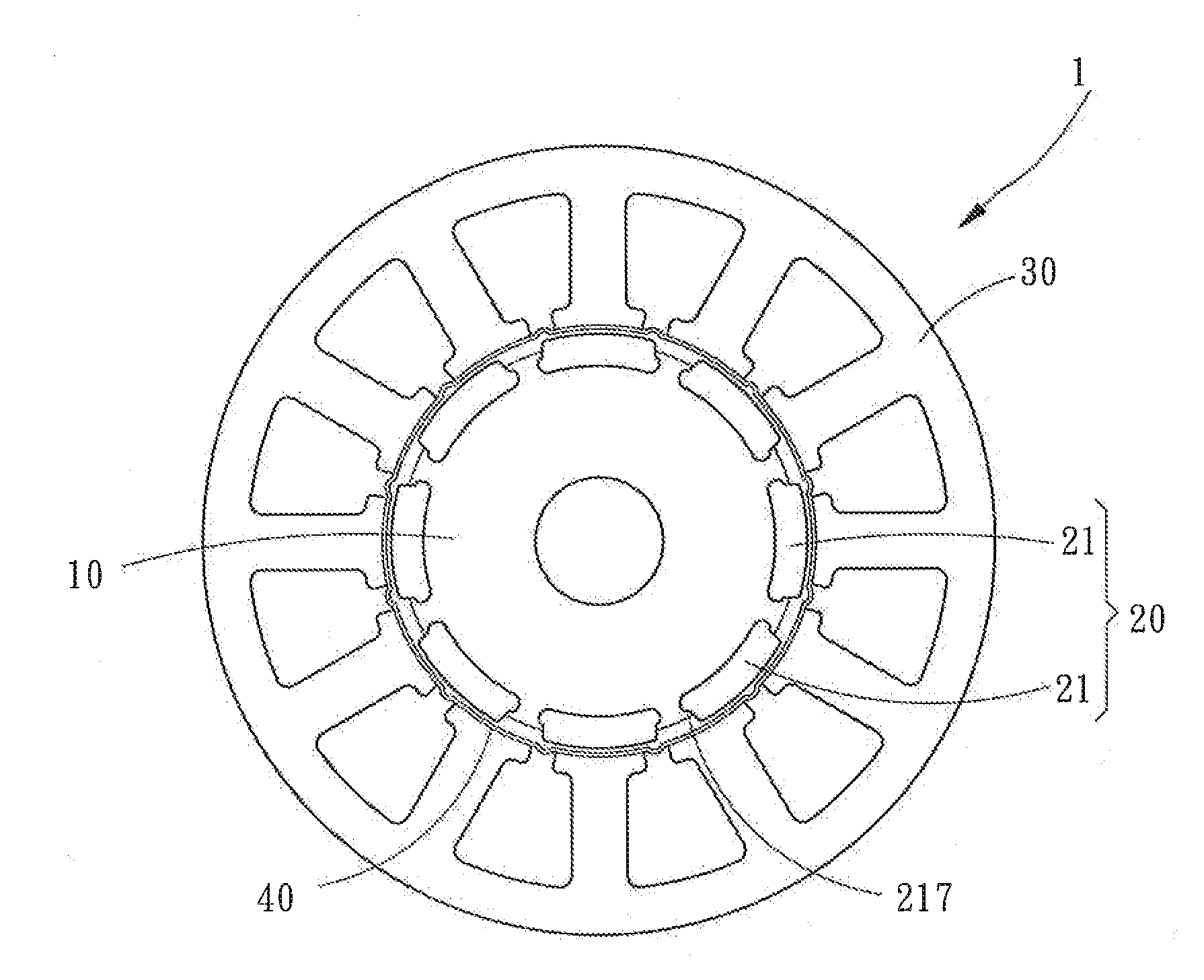
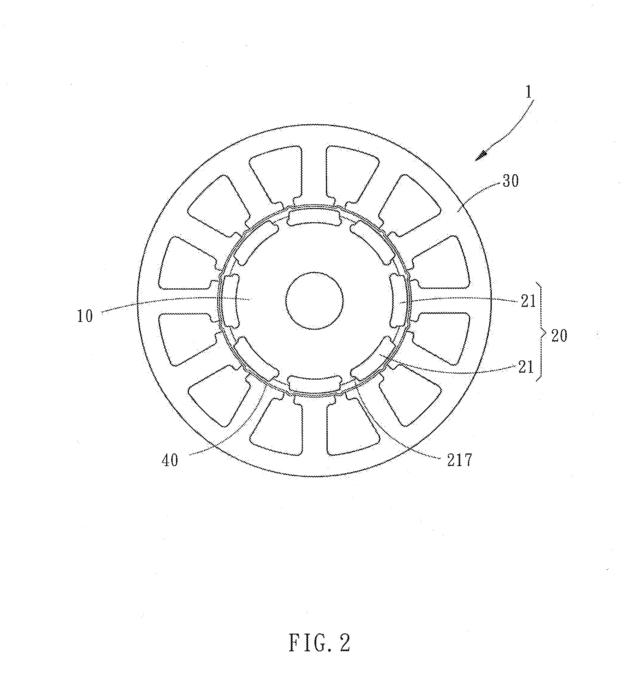
[0035]Referring to FIGS. 2, 3 and 6, a brushless permanent-magnet motor 1, 2 in accordance with first and second embodiments of the present invention is shown. The brushless permanent-magnet motor 1, 2 comprises a rotor 10, a magnet set 20, a stator 30, and a bushing 40.

[0036]The rotor 10 comprises an outer perimeter 11, and a plurality of insertion grooves 13 located at and spaced around the outer perimeter 11. Each insertion groove 13 defines a first accommodation space 131 and a second accommodation space 133 arranged in direction from the rotor 10 toward the stator 30. Further, the volume of the first accommodation space 131 is larger than the volume of the second accommodation space 133.

[0037]The magnet set 20 comprises a plurality of magnet components 21. Each magnet component 21 defines an outer arc surface 211, an opposing inner arc surface 213, two opposing lateral sides 215, and a flange 217 located at each lateral side 215 adjacent to the inner arc surface 213. Thus, the ...


PUM


Abstract

A brushless permanent-magnet motor includes a rotor, a magnet set mounted at the rotor, a stator coaxially surrounding the magnet set in a coaxial manner relative to the rotor, and a bushing set between the magnet set and the stator in a coaxial manner relative to the rotor and the stator. The stator has a plurality of teeth spaced around the inner perimeter thereof and a retaining crevice defined between the distal front end portions of each two adjacent teeth remote from the inner perimeter. The bushing has a plurality of locating ribs respectively engaged into the retaining crevices of the stator. Thus, the brushless permanent-magnet motor has a high level of structural stability, and can effectively reduce the air-gap flux density variation and instant cogging torque and torque ripples and solve vibration and noise problems.

Description

BACKGROUND OF THE INVENTION[0001]1. Field of the Invention[0002]The present invention relates to brushless motor technology, and more particularly to a brushless permanent-magnet motor, which has a bushing set between the magnet set and stator thereof to enhance the structural stability and to effectively reduce the air-gap flux density variation and instant cogging torque and torque ripples and solve vibration and noise problems.[0003]2. Description of the Related Art[0004]When compared to conventional motors, a brushless permanent-magnet motor has the benefits of high performance and high torque density, and therefore brushless permanent-magnet motors are widely used in different driving systems, such as marine propeller, lawn mower, elevator traction machine, etc. However, commercial brushless permanent-magnet motors commonly have the drawback of high cogging torque due to a large gap between the teeth of the stator, lowering the motor performance. This problem becomes more serio...

Claims


Application Information

Patent Timeline
Patent Type & Authority Applications(United States)
IPC IPC(8): H02K1/14H02K1/27
CPCH02K1/274H02K1/146H02K29/03H02K2213/03
Inventor LIU, CHIA-SHENGZHANG, YI-LI
Owner DURQ MACHINERY
Why Eureka
Try Eureka