LED array exposing apparatus and image forming apparatus using the same

an array and image technology, applied in the direction of electrographic process apparatus, instruments, printing, etc., can solve the problems of inability to reflect chip distance variation on light intensity compensation, inability to test printout by using initial led data, and inability to quickly achieve light intensity compensation. the effect of speeding up the execution speed and reducing the variation of image density

Inactive Publication Date: 2006-08-31
KYOCERA DOCUMENT SOLUTIONS INC
View PDF5 Cites 10 Cited by
  • Summary
  • Abstract
  • Description
  • Claims
  • Application Information

AI Technical Summary

Benefits of technology

[0023] According to the first invention, the LED light intensities are compensated, taking into consideration distance variations between the LED-array chips, a photoreceptor sensitivity and a development bias voltage, thereby reducing an image density variation and black or white longitudinal lines along the photoreceptor rotation direction.
[0024] Further, according to the second invention, the light intensity compensation can be easily executed merely by providing memory means for storing the prescribed light intensity compensation data and the distances between the LED-array chips.
[0025] Further, according to the third invention, light intensity compensation can be executed more efficiently, because prescribed standard driving values SDVs are compensated by using prescribed light intensity compensation data LICD; SDVs are further corrected by chip distance compensation coefficients CDCCs; and CDCCs are further adjusted by the photoreceptor sensitivity.
[0026] Further, according to the forth invention, the temperature data is stably obtained, thereby stabilizing the light intensity compensation.

Problems solved by technology

Particularly, the tandem color image forming apparatus is disadvantageously influenced on its color reproducibility, because the tandem color image forming apparatus simultaneously forms different color images by using a plurality of imaging units wherein the photoreceptor is different per color and the density variation becomes different per color if the sensitivity is compensated per color.
However, JP8-39860A (1996) has a disadvantage that the light intensity compensation is not rapid, because it takes some time to reach the target intensity.
Further, it has another disadvantage that the chip distance variation cannot be reflected on the light intensity compensation.
Further, JP8-183202 (1996) has a disadvantage that the test printout by using the initial LED data is required.
Therefore, it takes a long time to correct the light intensity.
It has another disadvantage that the exposure level compensation is not perfect, because the compensation is executed only at the portion where the white or black lines are generated.
Furthermore, it is difficult to perfectly suppress the sensitivity variation in or between the production lots.

Method used


Image

  • LED array exposing apparatus and image forming apparatus using the same
  • LED array exposing apparatus and image forming apparatus using the same
  • LED array exposing apparatus and image forming apparatus using the same

Examples


Embodiment Construction

[0034] The preferred embodiments are explained, referring to the drawings. It should be understood that the present invention is not limited to specifically described sizes, shapes and relative arrangements of the elements.

[0035] First, the structure of the image forming apparatus of the present invention is explained.

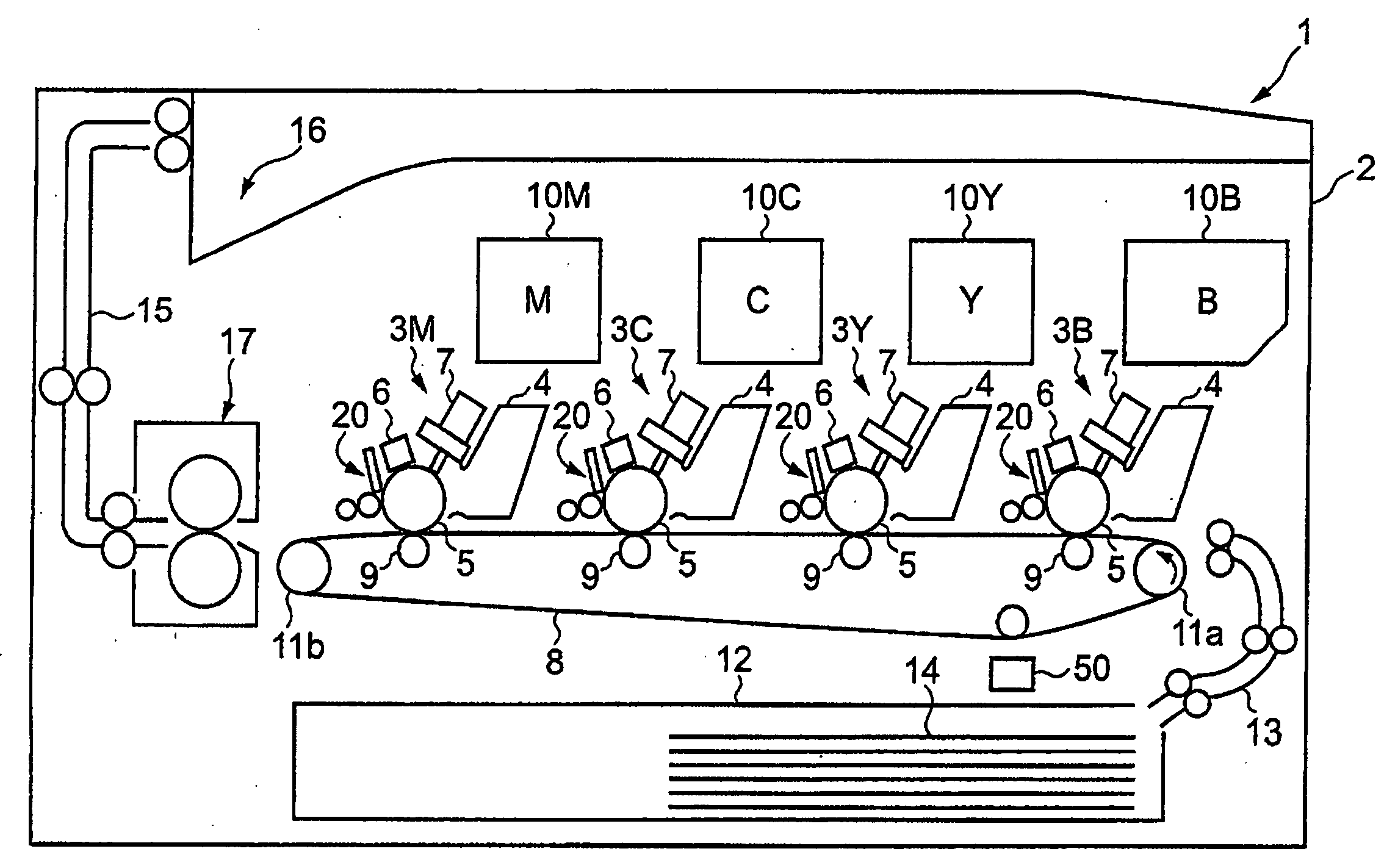
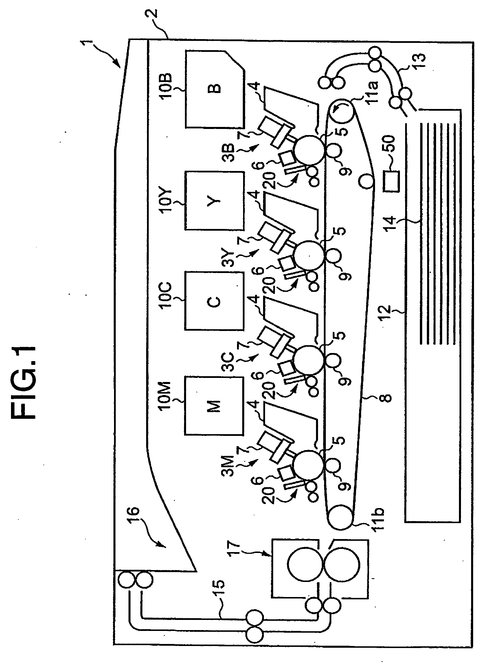
[0036]FIG. 1 is a schematic view of the image forming apparatus of the present embodiment.

[0037] The image forming apparatus ( an exemplary color printer 1) comprises a body 2, imaging units 3B, 3Y, 3C and 3M for black, yellow, cyan, magenta, respectively, toner hoppers 10B, 10Y, 10C and 10M, a paper supply cassettes 12, a paper supply guide 13, driving rollers 11a and 11b for a transport belt 8, a transfer roller 9, a fixing unit 17, a paper outlet guide 15, a paper outlet 16. Here, each of the imaging units 3B, 3Y, 3C and 3M comprises a developing unit 4, a photoreceptor 5, a main charging unit 6, an LED-array exposing unit 7, a cleaning unit 20.

[0038] A temperat...


PUM


Abstract

Provided are an LED-array exposing apparatus and image forming apparatus using the same wherein one or more LED-array chips which mount LEDs corresponding to pixels are employed. LED light intensities are compensated, taking into consideration distance variations between the LED-array chips, a photoreceptor sensitivity and a development bias voltage, thereby reducing an image density variation and black or white longitudinal lines along the photoreceptor rotation direction. The compensation circuit receives image signals and photoreceptor sensitivity, and compensates the light intensities, on the basis of prescribed ligh intensity compensation values and the LED-array chip distances. The compensated image signals together with timing clocks are sent to the LED-array exposing apparatus.

Description

BACKGROUND OF THE INVENTION [0001] (1) Field of the Invention [0002] The present invention relates to an LED-array exposing apparatus and an image forming apparatus using the same, wherein the density of electro-photographic copies is made as uniform as possible, even when the LED array is deviated from the pixel arrangement, or even when the sensitivities of the photoreceptors per se are varied, or are changed depending upon the temperature. [0003] (2) Description of the Related Art [0004] There are two types of image forming system, i.e., the direct image forming system and the indirect image forming system, for the copiers, printers and facsimiles. The image is directly formed on a sheet of paper in the direct image forming system, while the image is once transferred on an intermediate transfer medium such as the photoreceptor, thereby finally being transferred on the paper. The indirect image forming systems using plain paper are widely employed, except for the home use. [0005] ...

Claims


Application Information

Patent Timeline
Patent Type & Authority Applications(United States)
IPC IPC(8): B41J2/45B41J2/44B41J2/455G03G15/04
CPCB41J2/451G03G15/04054G03G2215/0409G03G15/326
Inventor OHBA, TADASHI
Owner KYOCERA DOCUMENT SOLUTIONS INC
Why Eureka
Try Eureka