Setting device of control system

a technology of a control system and a setting device, which is applied in the direction of electric controllers, testing/monitoring control systems, instruments, etc., can solve the problems of preventing the missing of the set operation, the wall side must be removed, and the communication line must be drawn out, so as to prevent the missing and the operation of the set operation is easy

Inactive Publication Date: 2006-03-30
MATSUSHITA ELECTRIC WORKS LTD
View PDF2 Cites 47 Cited by
  • Summary
  • Abstract
  • Description
  • Claims
  • Application Information

AI Technical Summary

Benefits of technology

[0012] It is the object of the present invention to provide a setting device of a control system which enable the setting operations to be performed easily, and can prevent the missing.
[0015] Therefore, the first setting means for setting the load devices which are the target of control to the operation terminal arranged on the arbitrary wall side as a format of an infrared ray remote controller, and the second setting means connected to the control unit via the communication line for setting the corresponding relationship between each of the operation terminals and the real load control terminal by the second setting means are formed integrally so that the setting operation may be executed easily. Further, it is possible to perform the setting of the control unit by the second setting means connected the communication line only by mounting the movable body portion on the reception unit. Further, when being not used, missing can be prevented by mounting the body portion on the reception unit.
[0017] According to the above structure, if the body portion which is detachably mounted on the reception unit is mounted on the reception unit, feeding is always performed from the control unit via the communication line, and it is possible to prevent the embedded battery which is used for setting the operation terminal by using the first setting means which is separated from the reception unit from being wasted. Preferably, after setting the embedded battery as a secondary battery, charging may be performed under the state that it is mounted on the reception unit.

Problems solved by technology

Therefore, in the pattern / the group setting, there is a troublesome problem that a plate of the wall side must be removed and a communication line has to be drawn out.
Further, if the setting is performed, there is a shortcoming that it is not possible to manage a remote controller which is not used in the outside places because of the change of the room or the change of the seasons, and thereby it is vulnerable to the missing.
On the other hand, in case of this setting device, in connection with the operation terminal which is arranged on an arbitrary wall side of the indoor room, since the control unit is arranged at a remote place such as a management room or an electricity-division room, there was a troublesome problem that the person had to go to the place in order to set the parameters with a remote controller.

Method used


Image

  • Setting device of control system
  • Setting device of control system
  • Setting device of control system

Examples


Embodiment Construction

[0031] Certain embodiments of the present invention will be described in greater detail with reference to the accompanying drawings.

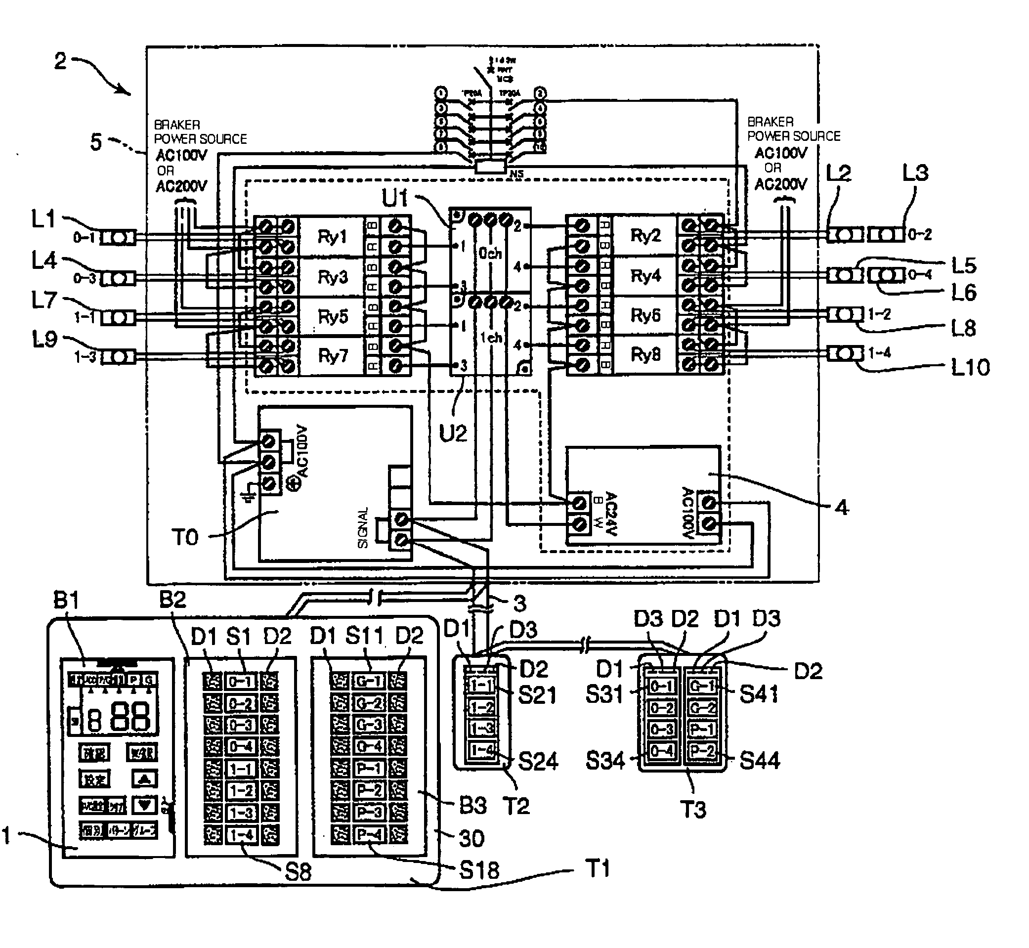
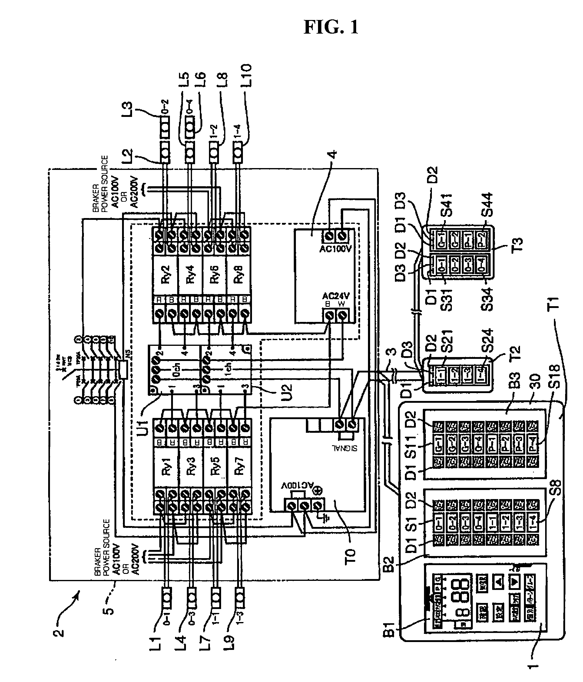
[0032]FIG. 1 is a block diagram showing an electrical structure of an illumination control system 2 provided with a setting device 1 according to the first embodiment of the present invention. In this illumination control system2, generally, a terminal unit U1, U2 for controlling a plurality relays Ry1-Ry8 (8 channel is shown in FIG. 8), which are load control terminals, and a plurality of operation terminals T1-T3 (3 terminals are shown in FIG. 3) are connected to a transmission unit T0 which is a control device via a common communication line 3. In response to the operations of each operation terminal T1-T3, the transmission unit T0 drives an illumination device through a corresponding one relay or a plurality of relays. Various kinds of illumination control such as a separate control, a group control, and a pattern control can be realized by setting...


PUM


Abstract

A setting device used in an illumination control system to realize a separate control, a group control, and a pattern control is disclosed. The object of the present invention is to enable a setting operation to be performed easily, and to prevent missing. In connection with the switch arranged on a wall side, the setting device sets a separate address of the separate control, a group number of the group control, and a pattern number of the pattern control by using an infrared ray communication. On the other hand, the corresponding relationships between each switch and the relay controlling the load actually is established by mounting the setting device on the operation terminal, and connecting it to the transmission unit via the communication line. Accordingly, it is possible to perform a setting operation easily by performing two kinds of setting as one pair. Further, missing can be prevented by mounting the movable setting device on the operation terminal arranged on the wall side.

Description

[0001] This application claims benefit under 35 U.S.C. § 119 from Japanese Patent Application No. 2004-275423, filed on Sep. 22, 2004, the entire content of which is incorporated herein by reference. BACKGROUND OF THE INVENTION [0002] 1. Field of the Invention [0003] The present invention relates to a setting device which is suitably used in a system for controlling many load devices, for example, in an illumination control system. [0004] 2. Description of the Related Art [0005] As a system for controlling many load devices such as the illumination control system, a control system is commercially used wherein a load control terminal including a relay for actually controlling a load device, and a plurality of the operation terminals such as a wall side switch are connected to a control unit via a communication line, and said control unit drives the load device through a corresponding load control terminal, or the plurality of load control terminals in response to the operations of ea...

Claims


Application Information

Patent Timeline
Patent Type & Authority Applications(United States)
IPC IPC(8): H02J3/00H02J3/14H02B1/24
CPCH05B37/0272H05B37/0254H05B47/18H05B47/195H05B47/19
Inventor HATEMATA, TAKESHI
Owner MATSUSHITA ELECTRIC WORKS LTD
Why Eureka
Try Eureka