Compact eye-tracked head-mounted display

a head-mounted display and compact technology, applied in the field of eye-tracking head-mounted displays, can solve the problems of integrating eye-tracking capability to these technologies, adding significant weight, volume, complexity,

Active Publication Date: 2014-12-11
AUGMENTED VISION +1
View PDF3 Cites 304 Cited by
  • Summary
  • Abstract
  • Description
  • Claims
  • Application Information

AI Technical Summary

Benefits of technology

[0022]FIGS. 5A-5D schematically illustrate an exemplary design of an optical see-through HMD in accordance with the present invention, with FIG. 5A showing the eye illumination and imaging paths, FIG. 5B showing the virtual dis

Problems solved by technology

Despite significant advancements and commercial availability of stand-alone HMD and eyetracking technologies, integrating these two stand-alone technologies imposes significant challenges in creating a compact, portable, accurate and robust system.
Although several pioneering efforts were made to develop ET-HMD technologies and to optimize these two technologies in a systematic approach, none of the existing technological solutions offers a truly portable, lightweight, and robust system that conforms to the form factor of an eyeglass-style display.
Few of these optical design methods are capable of creating a wide field-of-view, compact, and lig

Method used


Image

  • Compact eye-tracked head-mounted display
  • Compact eye-tracked head-mounted display
  • Compact eye-tracked head-mounted display

Examples


example 1

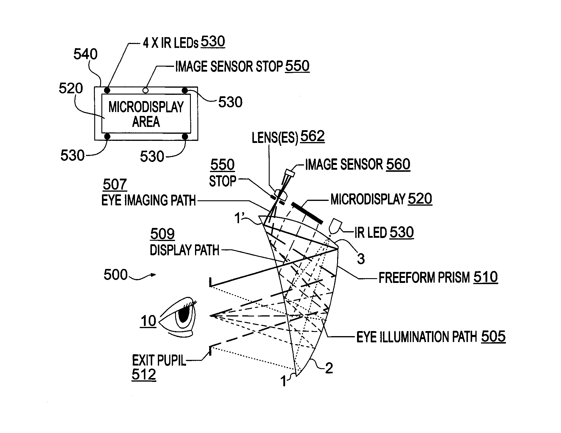
[0043]A first exemplary configuration 500 in accordance with the present invention utilizes wedge-shaped freeform prism 510 with two reflections, FIGS. 5A-5D. In this embodiment, the freeform prism 510 may serve as many as three core functions: (1) as an illumination optic that collimates the light from one or multiple NIR LEDs 530 to uniformly and non-invasively illuminate the eye area to be imaged; (2) as the core element of an eye imaging optic that captures NIR-illuminated eye images to enable eye movement tracking; and (3) as an eyepiece optic of an HMD system to view images on a microdisplay 520. These three unique optical paths may be combined by the same freeform prism 510 to achieve the capabilities of eyetracking and display. Additionally, the same prism 510 when cemented with a freeform corrective lens enables the see-through capability of an optical see-through HMD system. Alternatively, freeform prism 510 may omit the core function as an illumination optic.

[0044]The wed...

example 2

[0057]FIGS. 15A-15B schematically illustrate an exemplary design of a second configuration of the present invention, where the stop 1540 of the imaging system 1500 may surround the microdisplay 1520. The microdisplay plane is divided into three regions: an IR-transmissive area 1527 that allows collecting the rays by an IR sensor 1560 and which may serve as the stop 1540 for eye imaging on IR sensor 1560; the active area of the microdisplay 1520 (non-transmissive) corresponding to the active display area which blocks the IR rays from reaching the IR sensor 1560; and, a third non-transmissive frame 1523 between the IR transmissive and microdisplay areas corresponding to a physical frame of the microdisplay which also blocks the rays from reaching the IR sensor 1560. In the imaging system 1500 the respective optical axes of the prism 1510, microdisplay 1520, and IR sensor 1560 may be coaxial. As such, the IR sensor 1560 may be placed after the microdisplay 1520 to capture the image of ...

example 3

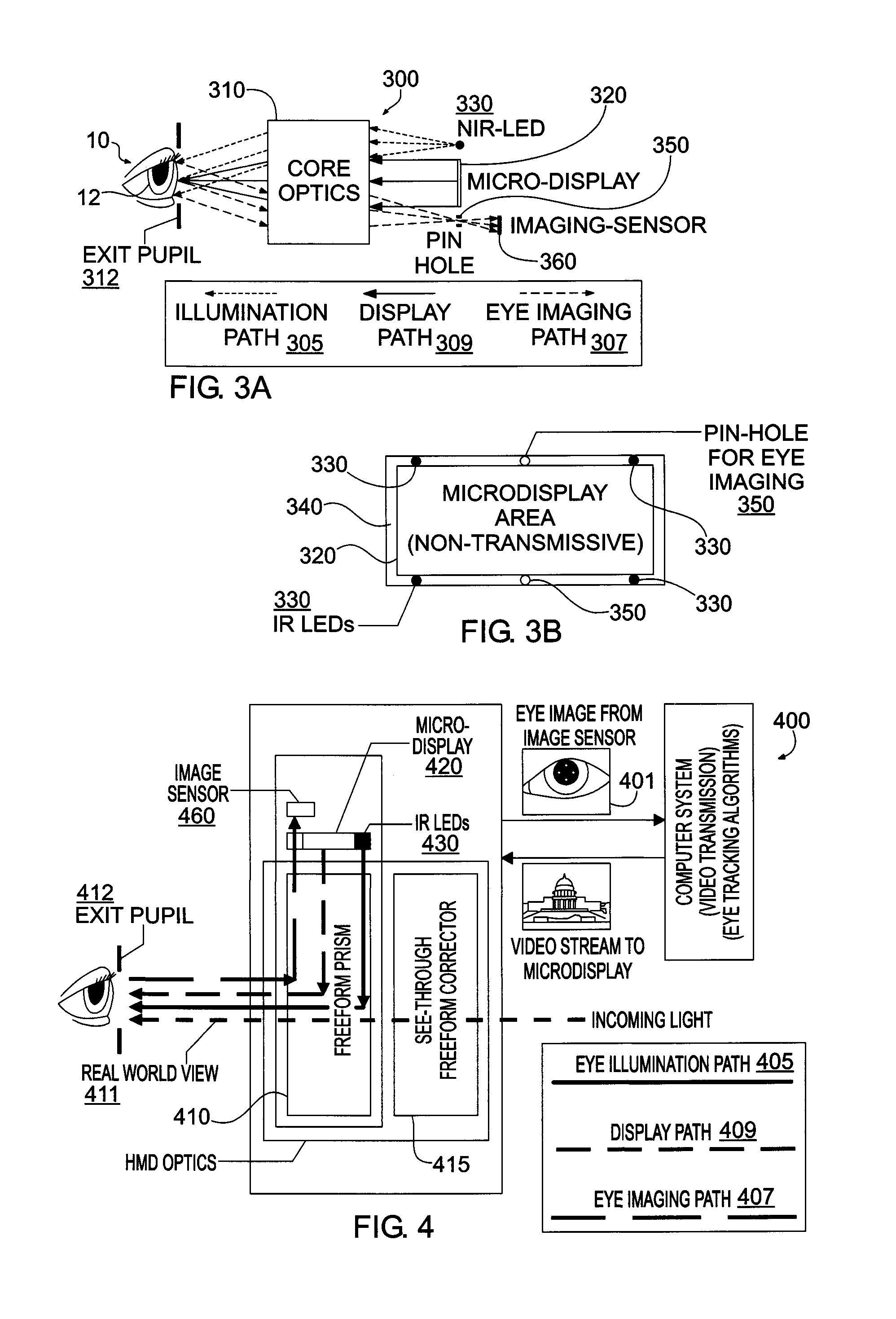
[0060]FIG. 16 schematically illustrates an exemplary design 1600 of the optical scheme shown in FIG. 3 utilizing on rotationally symmetric optics for the core optics 310. Instead of using a compact freeform based prism 510, a four-element viewing optics 1610 is used as the core optics 310 for display viewing, eye imaging and eye illumination. The microdisplay 1620 may be placed at the focal plane of the optics 1610. One light source 1630 (such as an NIR-LED) may be placed around the image source 1620. A pinhole-like stop 1640 and micro-imaging lens 1662 may also be placed around the edge of the image source 1620 to form eye images on the imaging sensor 1660. Additional light sources 1630 and imaging subsystems (micro-imaging lens 1662 and imaging sensors 1660) can be arranged around the image source 1620 as needed for different applications. In the exemplary design 1600 the respective optical axes of the display optics 1610 and microdisplay 1620 maybe coaxial, while the respective o...


PUM


Abstract

Eye-tracked head-mounted displays are provide which, in one aspect, may utilize the same optics for eyetracking and image viewing, with a selected portion of the optics used for an eyetracking optical path and a selected portion of the display optics used for an image viewing optical path.

Description

RELATED APPLICATIONS[0001]This claims the benefit of priority of U.S. Provisional Application No. 61 / 632,441, filed on Jan. 24, 2012 and claims the benefit of priority of U.S. Provisional Application No. 61 / 687,607, filed on Apr. 25, 2012 and claims the benefit of priority of U.S. Provisional Application No. 61 / 699,493, filed on Sep. 11, 2012, the entire contents of which applications are incorporated herein by reference.GOVERNMENT LICENSE RIGHTS[0002]This invention was made with government support under contract No. IIS1115489 awarded by the National Science Foundation. The government has certain rights in the invention.FIELD OF THE INVENTION[0003]The present invention relates generally to eye-tracked head-mounted displays, and more particularly, but not exclusively, to eye-tracked head-mounted displays which may utilize the same optics for eyetracking and image viewing, with a selected portion of the optics used for an eyetracking optical path and a selected portion of the display...

Claims


Application Information

Patent Timeline
IPC IPC(8): G02B27/01G06F3/01
CPCG06F3/013G02B17/086G02B17/0896G02B27/017G02B27/0172G02B27/0093G02B2027/0187G02B2027/011G02B2027/0138G02B5/04
Inventor HUA, HONGGAO, CHUNYU
Owner AUGMENTED VISION
Why Eureka
Try Eureka