Method for assessing function of the visual system and apparatus thereof
- Summary
- Abstract
- Description
- Claims
- Application Information
AI Technical Summary
Benefits of technology
Problems solved by technology
Method used
Image
Examples
example 1
Device
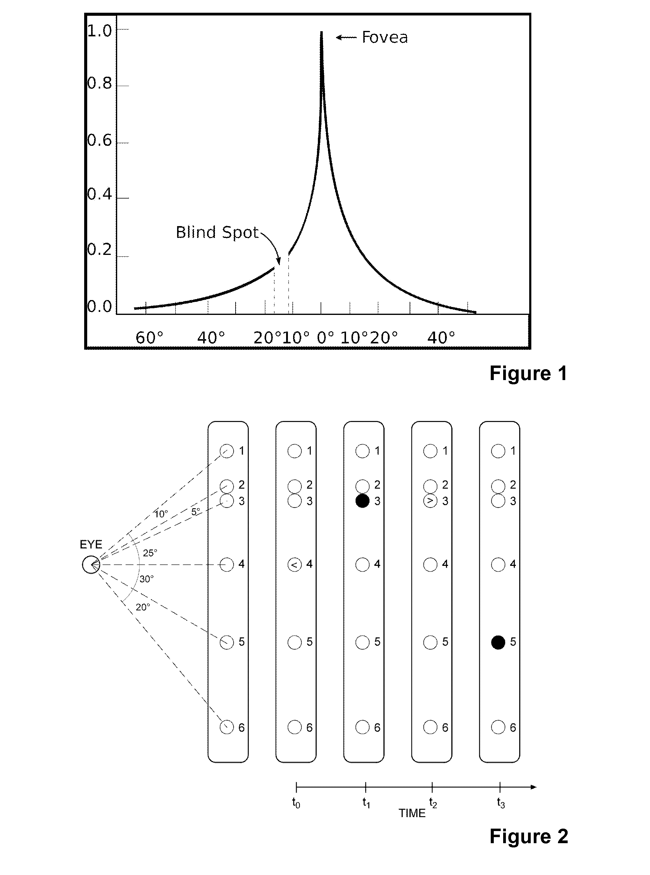
[0137]A preferred embodiment of a device for utilizing the method of the invention consists of a display unit, which is capable of providing both fixation object FO, which is designed so that it is only detectable by foveal vision, and saccade triggering or smooth pursuit triggering stimuli (STS or SPTS) which are designed to the needs of the function of the visual system which are being assessed or practised. In the preferred embodiment several display units can be used (FIG. 2) They can be located at various angular distances in relation to the eye of a person. In FIG. 2, consecutive angular distances 10, 5, 25, 30, and 20 degrees are used. According to this invention, the eye makes saccadic eye movements between display units 1-6. Table 1 summarizes all the possible saccades which the eye can make between the six display units. In Table 2 all possible angular distances are arranged in order.
[0138]FIG. 2 illustrates a sequence of an examination according to the invention: At...
example 2
Evaluation of Visual Field
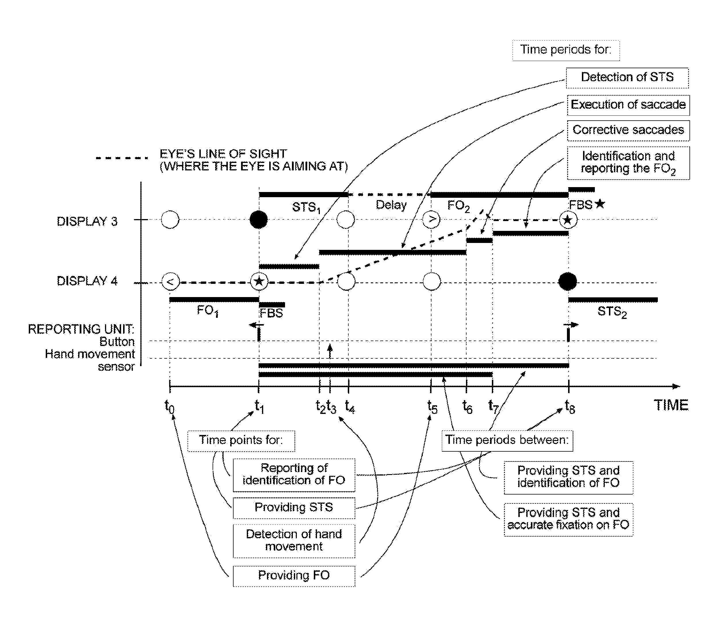
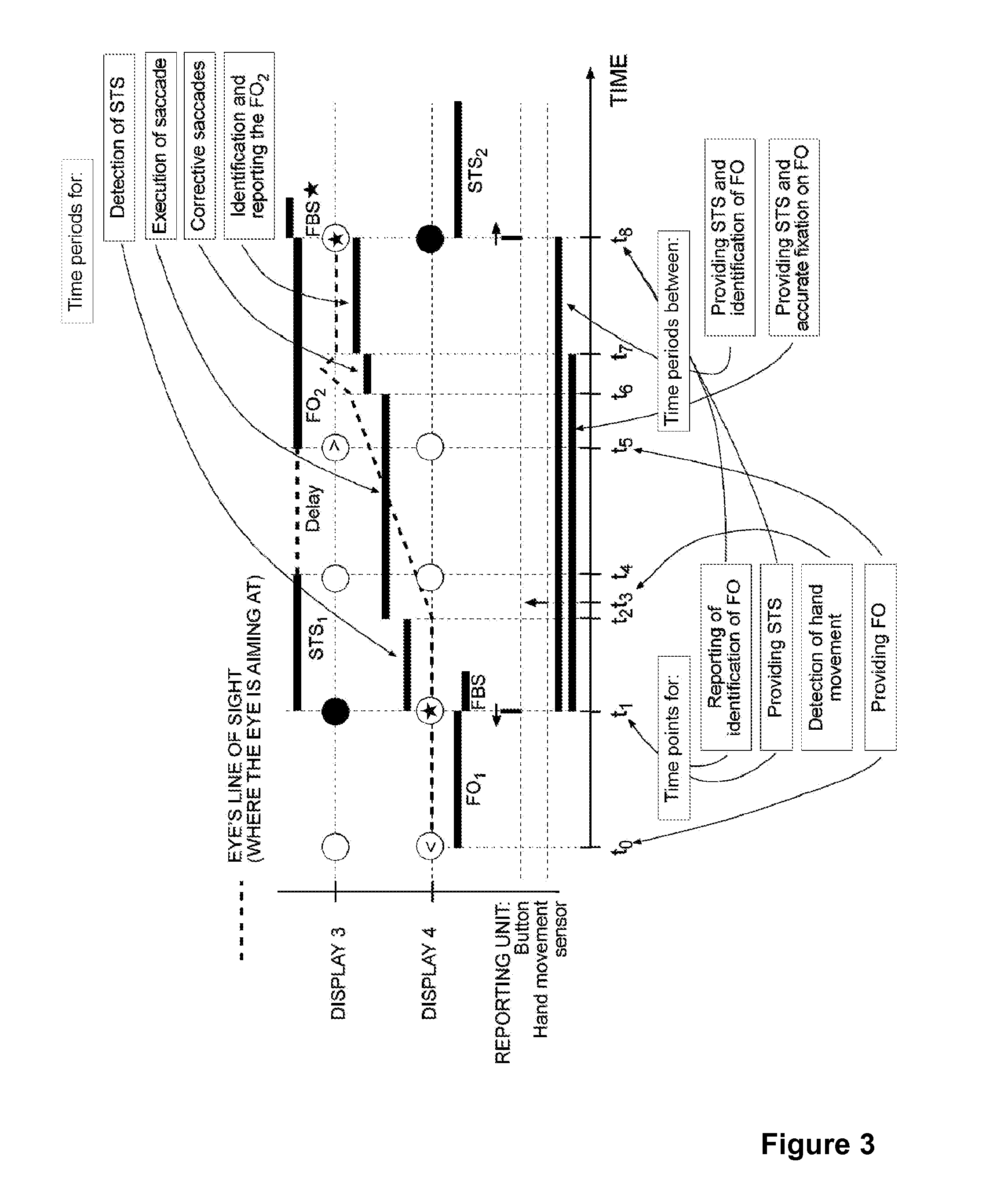
[0139]Evaluation of the visual field of an eye of a person can be carried out e.g. as follows (see FIG. 3):
[0140]The sequence illustrated in FIG. 3 starts with providing a saccade triggering stimulus STS1 and ends in correctly reporting the identification of FO2. Only display units 3 and 4 (see FIG. 2) are visible in this illustration. The responses of the person are also illustrated: the movement of the hand towards the display unit is recorded by a hand movement sensor and choice of the button the person has pressed reports the identification of the fixation object FO.
[0141]Fixation object FO1 is provided at display unit 4 at time point to. When a person identifies it (an arrow to the left) and reports by pressing a correct button (left button) at time point t1, the fixation object FO1 is extinguished and a saccade triggering stimulus STS1 is provided at display unit 3 which is located 25 degrees apart from display unit 4. If standard visual field examina...
example 3
Distracting Fixation Objects
[0144]FIG. 4 illustrates the use of visual search distractor fixation objects (named ‘distractor object’ in FIG. 4). At time point t5 one or many optional distractor objects are provided to the display unit(s) n in addition to FO2 provided to the display unit 3. If the person has detected saccade triggering stimulus STS1 and has made a saccade toward display 3, he or she finds easily and without delay the FO2 and reports the identification of it. Because the distractor objects resemble FO but are distinguishable from it by careful inspection, finding the FO among many distractor objects solely by visual search without detecting first the STS becomes difficult and makes the reaction time for reporting the correct identification of FO longer compared to the situation where FO is found with the help of detecting the STS which triggers a saccade towards FO.
TABLE 3Results from measuring the time period for identification and reporting the fixation object (see ...
PUM
 Abstract
Description
Claims
Application Information
 - R&D
- Intellectual Property
- Life Sciences
- Materials
- Tech Scout
- Unparalleled Data Quality
- Higher Quality Content
- 60% Fewer Hallucinations
Browse by: Latest US Patents, China's latest patents, Technical Efficacy Thesaurus, Application Domain, Technology Topic, Popular Technical Reports.
© 2025 PatSnap. All rights reserved.Legal|Privacy policy|Modern Slavery Act Transparency Statement|Sitemap|About US| Contact US: help@patsnap.com


