Ultra low-profile connectors

a technology of low-profile connectors and connectors, which is applied in the direction of electrical equipment, coupling device connections, printed circuits, etc., can solve the problems of increasing input/output density requirements, increasing the difficulty of maintaining the desired co-planarity, and increasing the number of contacts, etc., to achieve the effect of long contact wipe distance and low profil

Inactive Publication Date: 2014-12-11
SAMTEC
View PDF0 Cites 6 Cited by
  • Summary
  • Abstract
  • Description
  • Claims
  • Application Information

AI Technical Summary

Benefits of technology

[0016]To overcome the problems described above, preferred embodiments of the present invention provide a mezzanine connector and an edge connector each with low profiles and long contact wipe distances.

Problems solved by technology

One problem with miniaturized connectors arises from the increased precision (i.e., tighter tolerances) of placement necessary to produce the proper positioning and connection of the connector contacts onto the electrical device.
This problem is exacerbated by the ever-increasing input / output (I / O) density requirements demanded of the progressively smaller connectors by increasingly miniaturized electrical devices.
As the number of contacts increases in each connector, it becomes more and more difficult to maintain desired levels of co-planarity, while maintaining connection of all of the contacts to a substrate.
However, conventional mezzanine connectors have a number of problems, as described below.
As shown in FIGS. 6 and 7 of U.S. Pat. No. 6,702,590, one problem with conventional mezzanine connectors is that the distance between the substrates is limited by the heights of the terminal and the socket.
As shown in FIGS. 48 and 49 of U.S. Pat. No. 6,702,590, another problem with conventional mezzanine connectors is that reducing the heights of the terminal and / or socket also reduces wipe distances of the contacts when the terminal and socket are connected, which may negatively affect the performance and longevity of the electrical connection.
A short wipe distance may cause poor electrical performance due to a weak mechanical connection between the corresponding contacts.
Furthermore, poor electrical performance in mezzanine connectors may result from a force normal to the mating direction of the terminal and socket being insufficient to wipe off the oxides and other substances from the corresponding contacts.
However, if the force normal to the mating direction of the terminal and the socket is too great, one or more of the contacts may bend or buckle when the terminal and socket are mated.
Accordingly, proper alignment between the terminal and the socket during mating is important to help ensure that the force normal to the mating direction of the terminal and the socket is sufficient to wipe off the oxides and other substances from the corresponding contacts, yet insufficient to cause any of the contacts to bend or buckle.
As an example, cantilevered contacts are particularly susceptible to variations in the force normal to the mating direction of the terminal and the socket.
As shown in FIG. 1 of U.S. Pat. No. 6,918,776, an additional problem with conventional mezzanine connectors is that the distance between the substrates is also limited due to both the terminal and the socket being mounted on the surface of substrate.
A further problem with conventional connectors is the use of multiple folded contacts in the terminal and socket that require the width of the connector to be much wider.

Method used


Image

  • Ultra low-profile connectors
  • Ultra low-profile connectors
  • Ultra low-profile connectors

Examples


Embodiment Construction

[0054]Preferred embodiments of the present invention will now be described in detail with reference to FIGS. 1 to 68. Note that the following description is in all aspects illustrative and not restrictive and should not be construed to restrict the applications or uses of the present invention in any manner.

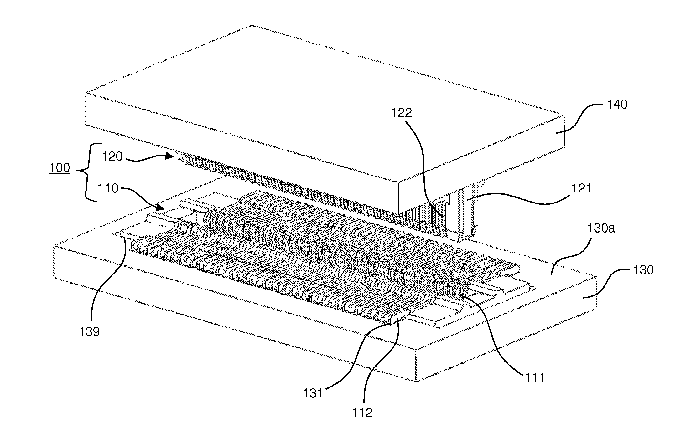
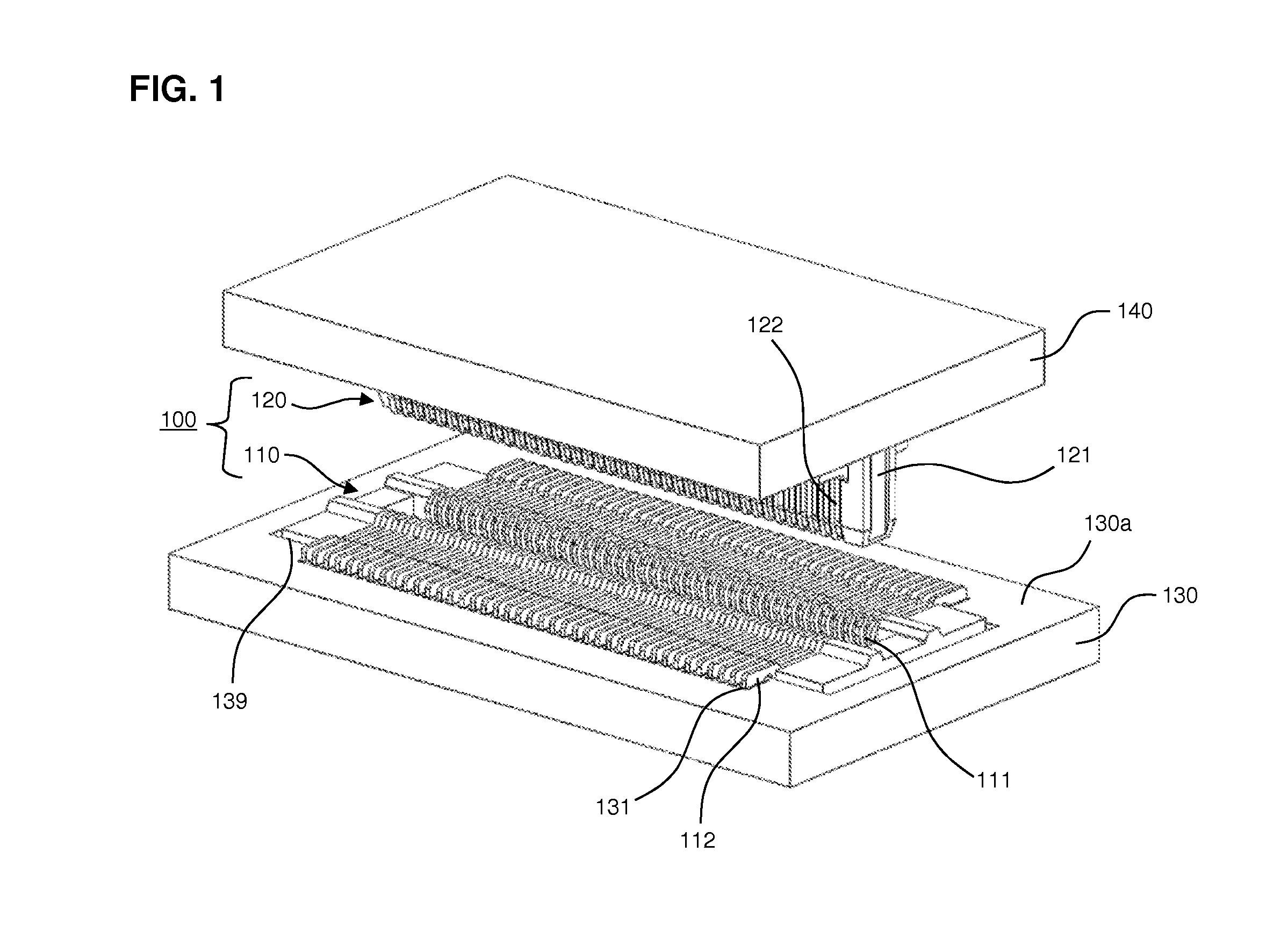
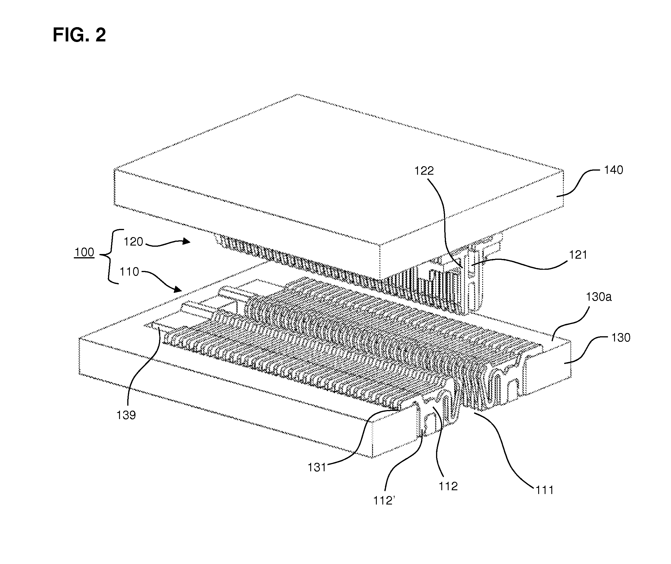
[0055]FIGS. 1-9 show a connector 100 in accordance with a first preferred embodiment of the present invention. FIGS. 1 and 2 are a perspective view and a cross-sectional perspective view of the connector 100, which includes a socket 110 and a terminal 120 that are respectively connected to a first substrate 130 and a second substrate 140. FIGS. 3 and 4 are a perspective view and a cross-sectional perspective view of the socket 110 being inserted into the first substrate 130. FIG. 5 is a cross-sectional end view of the socket 110, the terminal 120, the first substrate 130, and the second substrate 140. FIGS. 6-9 are perspective views and cross-sectional views of the socket 110, th...


PUM


Abstract

A connector system includes a first connector including first contacts arranged around a pass-through hole or a recess, the first connector being configured to be located in a cut-out of a first substrate such that the first contacts are connected to the first substrate, and a second connector including second contacts arranged around a beam, the second connector configured to be connected to a second substrate such that the second contacts are connected to the second substrate. The pass-through hole or the recess extends in a mating direction of the first connector and the second connector, and the beam of the second connector is configured to extend into the pass-through hole or the recess of the first connector when the first connector and the second connector are mated such that the first contacts engage with respective ones of the second contacts.

Description

CROSS-REFERENCE TO RELATED APPLICATIONS[0001]This application is a Continuation-In-Part of U.S. patent application Ser. No. 13 / 688,392 filed on Nov. 29, 2012, currently pending, the entire contents of which are hereby incorporated by reference.BACKGROUND OF THE INVENTION[0002]1. Field of the Invention[0003]The present invention relates to electrical connectors. More specifically, the present invention relates to mezzanine and edge connectors having low profiles.[0004]2. Description of the Related Art[0005]Electrical connectors are used to allow electrical devices, such as substrates or printed circuit boards, to communicate with one another. A connector may be thought of as having two portions, a first portion which connects to a first electrical device and a second portion which connects to a second electrical device to be put into communication with the first device. To connect the two electrical devices, the two portions of the connector are mated together.[0006]Each connector in...

Claims


Application Information

Patent Timeline
Patent Type & Authority Applications(United States)
IPC IPC(8): H01R12/71
CPCH01R12/718H01R12/7052H01R12/716H01R12/73
Inventor RYAN, CRAIG FRANCISSWITZER, TOBIAS SCOTTREIDINGER, GREGORY LEOSCHMELZ, DALE FRANCISOUYANG, WILLIAM CHIENG
Owner SAMTEC
Why Eureka
Try Eureka