Power grid stabilization system and power grid stabilization method

a power grid and stabilization system technology, applied in the direction of electric variable regulation, process and machine control, instruments, etc., can solve problems such as general instability in output, and achieve the effect of suppressing disturbances

Active Publication Date: 2014-12-11
HITACHI LTD
View PDF23 Cites 21 Cited by
  • Summary
  • Abstract
  • Description
  • Claims
  • Application Information

AI Technical Summary

Benefits of technology

[0009]An object of the present invention is to provide a power system stabilization system and a power system stabilizat

Problems solved by technology

The typical renewable energies mentioned above are dispersed power sources, and they are generally u

Method used


Image

  • Power grid stabilization system and power grid stabilization method
  • Power grid stabilization system and power grid stabilization method
  • Power grid stabilization system and power grid stabilization method

Examples


first embodiment

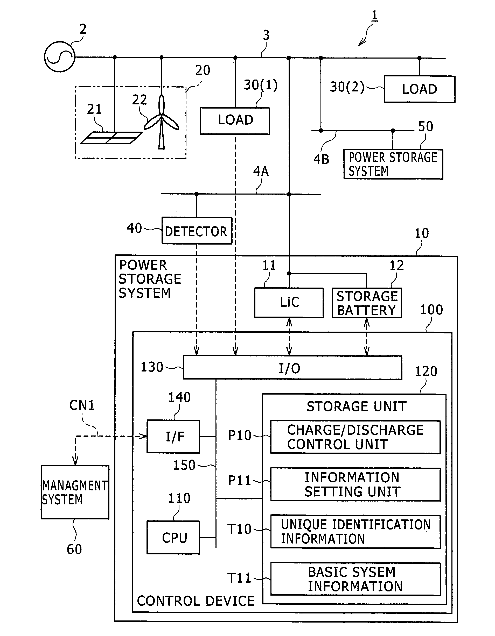
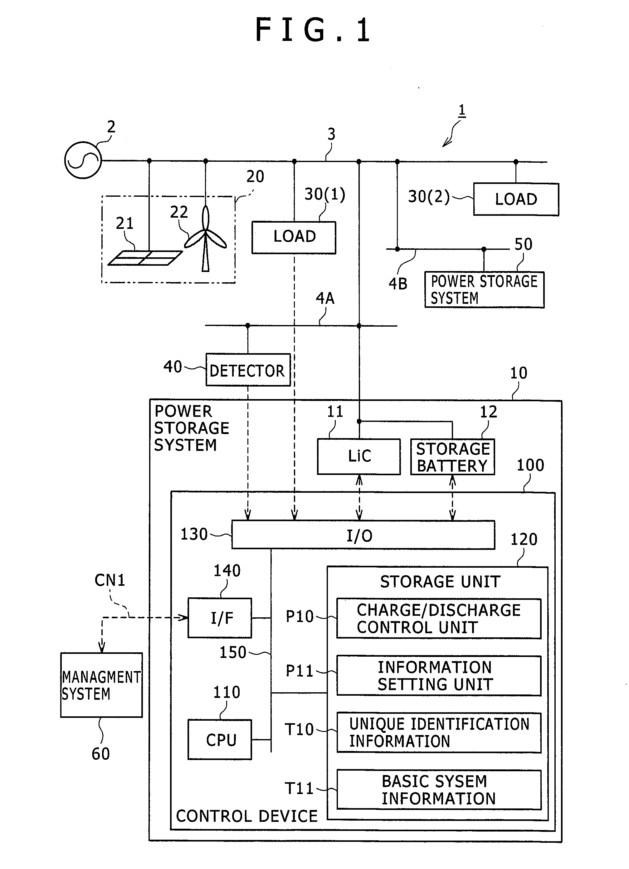
[0029]FIG. 1 shows a power system configuration including a power system stabilization system 1 according to a first embodiment of the present invention. For example, a substation 2 which transforms the power received from a large-scale centralized power station into a predetermined voltage and distributes the transformed power is connected with a transmission line 3 from which plural distribution lines 4A and 4B are branched. When not particularly distinguished, the distribution lines 4A and 4B will be each referred to as a “distribution line 4.”

[0030]The transmission line 3 or distribution lines 4 are connected with power storage systems 10 and 50. The power storage system 10 is an object of control in the present embodiment. The other power storage system 50 is not an object of control in the present embodiment. It is shown for comparison purposes. The configuration of the power storage system 10 will be described later.

[0031]A dispersed power source 20 is connected to the transm...

second embodiment

[0121]A second embodiment will be described with reference to FIG. 12. The following embodiments including the present embodiment represent example modifications of the first embodiment. The following embodiments will therefore be described centering on their differences from the first embodiment. In the present embodiment, operation mode is automatically switched according to the state of communication between the management system 60 and the power storage system 10.

[0122]FIG. 12 is a flowchart for mode switching processing performed by a power storage system 10. The power storage system 10 is assumed to periodically communicate with the management system 60 to determine the state of communication (S50).

[0123]Upon detection of occurrence of a communication failure (S50: YES), the power storage system 10 changes to autonomous mode (S51). In autonomous mode, the power storage system 10 immediately starts compensation operation upon detection of a disturbance by the detector 40 withou...

third embodiment

[0127]A third embodiment will be described with reference to FIG. 13. The third embodiment will be described based on a case in which plural disturbances to be compensated for in different ways are detected.

[0128]FIG. 13 is a flowchart for compensation operation processing to be performed by a power storage system 10 according to the present embodiment. This processing entirely includes the processing performed insteps S20 through S27 shown in FIG. 7. Furthermore, this processing includes additional, steps S60 and S61.

[0129]For example, after determining the location of a disturbance (S21: YES), the power storage system 10 determines whether any other disturbance of a different inclination has occurred (S60). A disturbance of a different inclination is a disturbance which differs in content from the disturbance detected in step S20 and which requires a different type of compensation operation to be performed. Assume, for example, that a disturbance has resulted from an increase in t...


PUM


Abstract

Plural distributed power storage systems are used to stabilize a power system. Plural power storage systems 10 are provided in a power system. The power storage systems 10 are connected to a management system 60 via a communication network CN1. The power storage systems each include a power storage device 11, 12, and a control device 100 for controlling the power storage device. The control device stores performance information about the power storage system including the control device, location information indicating a location in the power system of the power storage system including the control device, and order information indicating an order of operation allocated to the power storage system including the control device. When a disturbance occurs in the power system, the control device performs a predetermined compensation operation based on the location information and the order information, and then returns to a preset stand-by state.

Description

TECHNICAL FIELD[0001]The present invention relates to a power system stabilization system and a power system stabilization method.BACKGROUND ART[0002]Recently, the use of renewable energies is being expanded from the viewpoint of securing energy security and reducing the burden on the global environment. Among the dispersed power sources making use of renewable energies, solar photovoltaic generation (may hereinafter be referred to as “PV”) and wind-power generation are known.[0003]The typical renewable energies mentioned above are dispersed power sources, and they are generally unstable in output compared with conventional thermal power generation or hydraulic power generation. Therefore, in cases where dispersed power sources are connected to a power system, a technical measure for dealing with sharp output variations is required.[0004]In Patent Literature 1, a configuration in which the output variations of dispersed power sources are suppressed using NAS (sodium-sulfur) batterie...

Claims


Application Information

Patent Timeline
IPC IPC(8): G05F1/66
CPCG05F1/66H02J3/32H02J3/46H02J2300/20H02J3/381
Inventor NAMBA, SHIGEAKIHONZAWA, ATSUSHITAKEUCHI, HIROTOTSUNODA, KAZUYUKIIMAI, MIKA
Owner HITACHI LTD
Why Eureka
Try Eureka