Method for adjusting the vibration frequency range of a sound producing device with vibrating tongues

a technology of vibrating tongue and vibration frequency range, which is applied in the direction of mechanical time indication, acoustic indication, instruments, etc., can solve the problems of difficult implementation, difficult securement, and adding sliding load members, so as to improve the securing of the pin-barrel, facilitate the adjustment, and improve the acoustic transmission to the radiating components of the watch.

Active Publication Date: 2014-12-18
MONTRES BREGUET
View PDF12 Cites 4 Cited by
  • Summary
  • Abstract
  • Description
  • Claims
  • Application Information

AI Technical Summary

Benefits of technology

[0016]One advantage of the sound producing device provided with means of adjusting the frequency range of the musical pin-barrel lies in the fact the general length of the vibrating tongue or tongues may easily be adjusted without having to change the pin-barrel. This makes it possible to adapt the frequency range, via at least one jaw fixed to a support, and via a counter-support, by locally clamping an end portion of the tongue or tongues, when the comb of the pin-barrel is secured to the suppo

Problems solved by technology

The solution of U.S. Pat. No. 2,755,697, of adding a sliding load member, is difficult to implement in the case of a device for incorporation in a watch, due to the miniaturisation required.
Further, it is unreliable, as it is

Method used


Image

  • Method for adjusting the vibration frequency range of a sound producing device with vibrating tongues
  • Method for adjusting the vibration frequency range of a sound producing device with vibrating tongues
  • Method for adjusting the vibration frequency range of a sound producing device with vibrating tongues

Examples


first embodiment

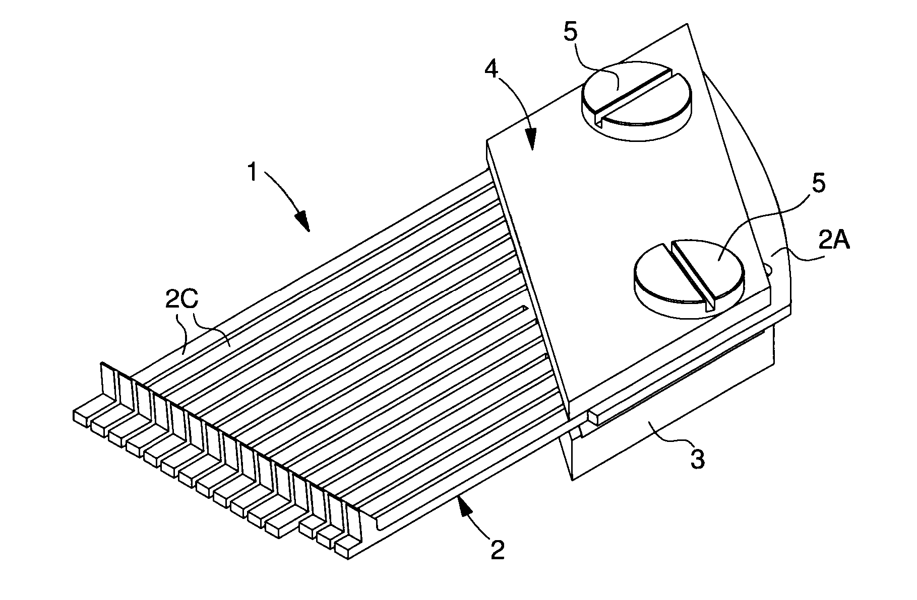
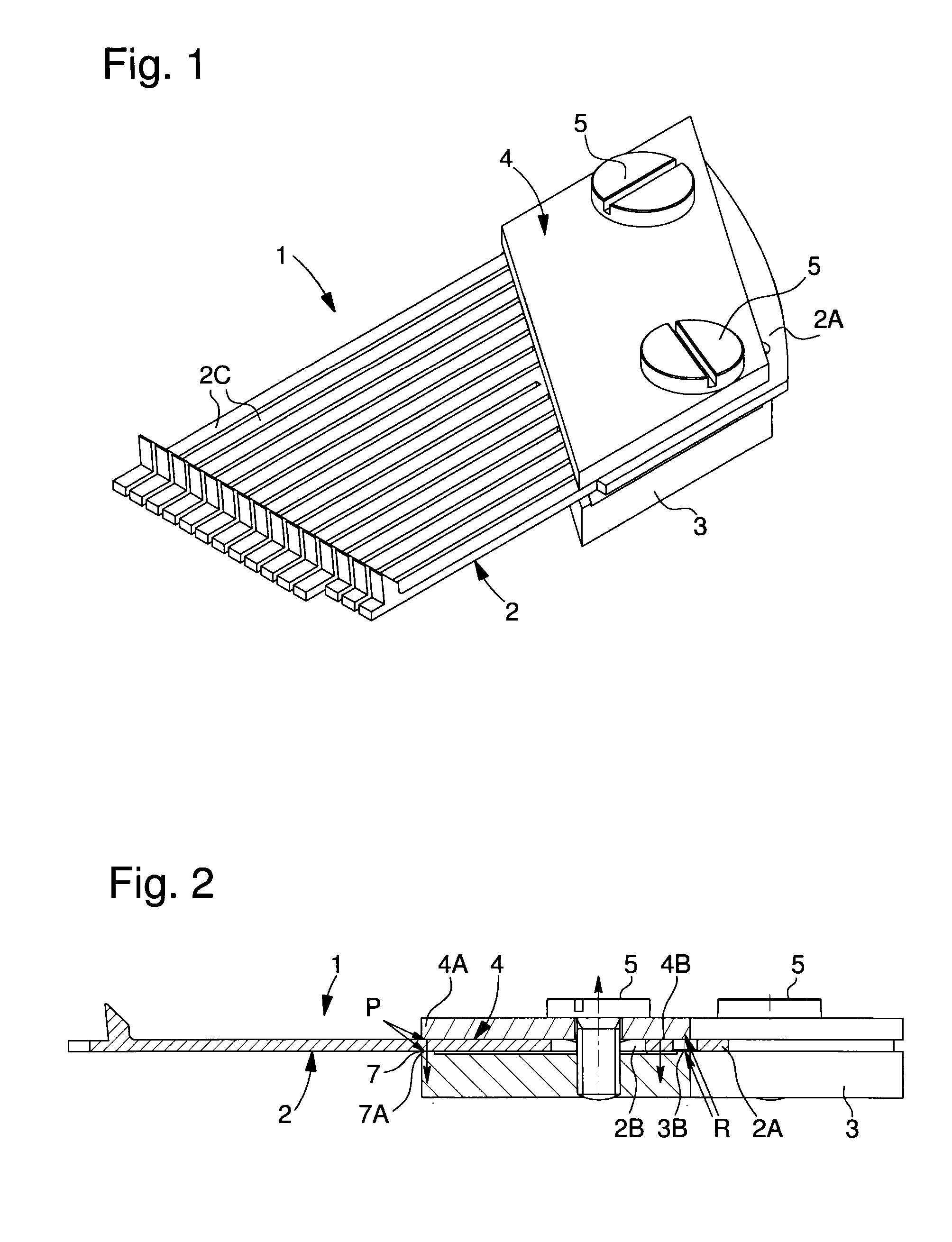
[0039]In FIGS. 1 and 2, partly described above, counter-support 7 is directly formed by support 3, which has a rib 7A on the front edge thereof and the front edge of jaw 4 also has a rib 4A, which is positioned facing rib 7A of the support to form a clamp. This clamp defines first clamping points on an end portion of the tongue or tongues of the pin-barrel.

[0040]To improve tightening, the back edge of support 3 and the back edge of jaw 4 also have a rib 3B, 4B respectively, which are positioned facing each other. Thus, comb 2A and the tongue or tongues 2C are in contact with the support and the jaw only on the ribs, so that the force exerted by the screw on jaw 4 is converted into localised clamping pressure on the tongue and on the comb. This pressure is concentrated on the clamping regions.

second embodiment

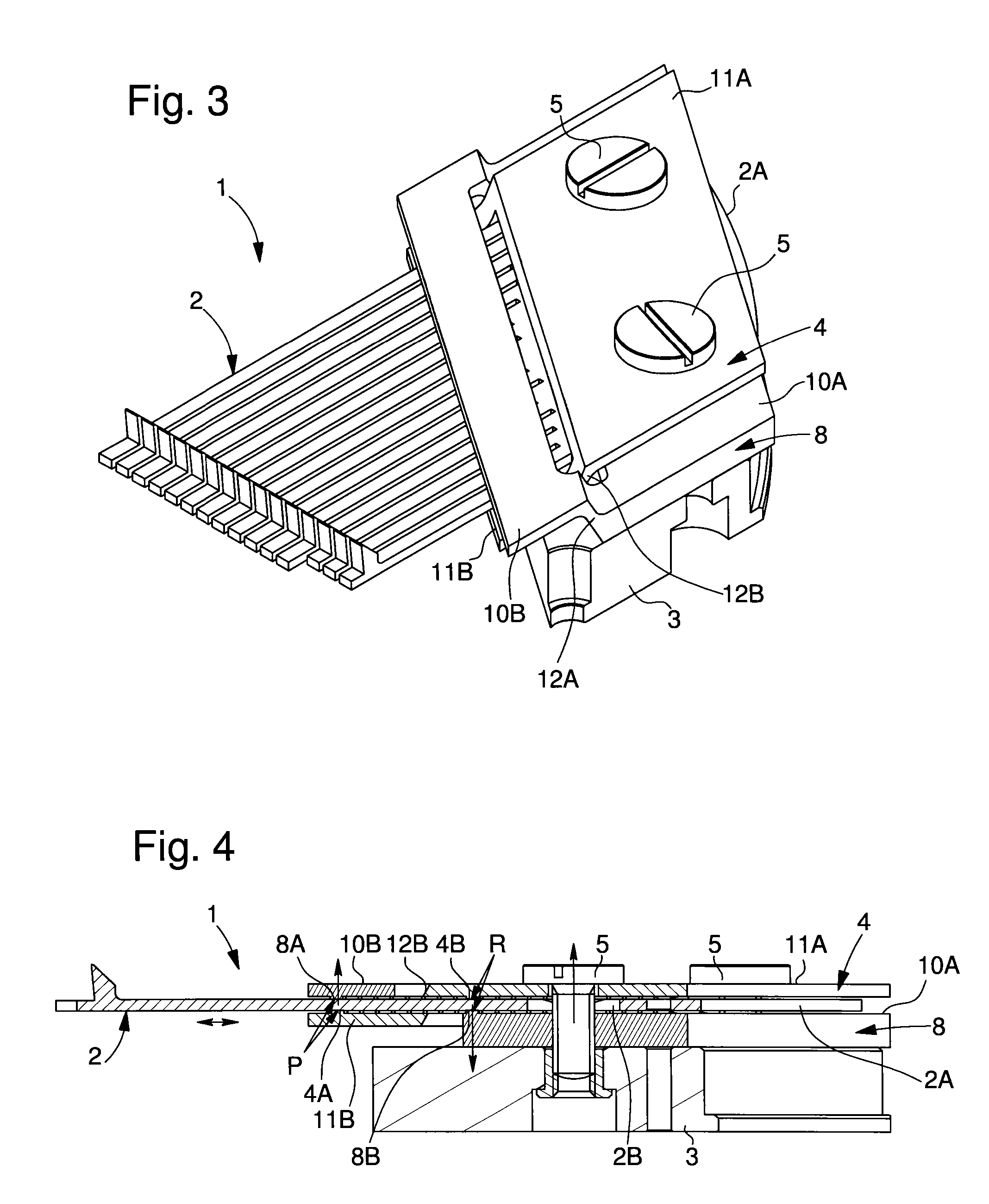
[0041]In a second embodiment shown in FIGS. 3 and 4, the counter-support is comprised in a part 8 independent of support 3, which thus forms a second jaw 8 or counter-support jaw. According to this embodiment, the two parts forming jaws 4, 8 are adapted to intersect in the manner of a pair of crossed scissors.

[0042]Each jaw 4, 8 includes two plates 10A, 10B, 11A and 11B, which are situated in two substantially parallel planes and are joined by a cross-shaped member 12A, 12B, one of which is a first loop 12A and the other is a second inclined loop 12B. This second inclined loop 12B is inserted into the first loop 12A. The pin-barrel tongues pass between the first and second loops. The plates have ribs facing each other to form a front clamping region P and a back clamping region R. Front clamping region P is arranged to clamp an end portion of the pin-barrel tongues, in order to adjust the frequency range of said pin-barrel. Clamping region P may be defined as the first clamping poin...

third embodiment

[0047]the sound producing device is shown in FIGS. 5 and 6. This time, the two jaws 4, 8 cooperate at their distal ends forming a sort of pivot. Behind the pivot, each jaw has a rib 4A, 8A defining clamping region P. Thus, tightening the tightening screw or screws 5 moves ribs 4A, 8A of the pin-barrel tongue or tongues closer together.

[0048]For forming the pivot line, there are several possibilities. More specifically, on its two lateral sides towards the front, the second jaw 8, which forms a counter-support, carries hooks 20 open towards the back of the jaw. Two lugs 21 of the front edge of first jaw 4 are inserted into these hooks 20 to form the pivot. The two jaws 4 and 8 are wider than the set of vibrating tongues of the pin-barrel. Further, the assembly of the pivots leaves an aperture open for the passage of the tongues.


PUM


Abstract

The invention concerns a method for adjusting the vibration frequency range of a sound producing device with vibrating tongues. The device includes an assembly formed of a comb extended by at least one vibrating tongue, said comb having at least one hole for the securing thereof to a support by means of a support jaw and of a tightening element traversing the support jaw and the hole in the aforecited comb. According to the method, the frequency range is adjusted by reducing the free length of the vibrating tongue or tongues by the localised clamping of said tongues between the support jaw and a local counter-support.

Description

[0001]This application claims priority from European Patent Application No. 13172119.3 filed 14.06.2013, the entire disclosure of which is incorporated herein by reference.FIELD OF THE INVENTION[0002]The invention relates to a method for adjusting the vibration frequency range of a sound producing device with one or more vibrating tongues or strips.BACKGROUND OF THE INVENTION[0003]The first musical box, created in 1796 by Antoine Fabre, was formed of a cylinder provided with pins and a set of tongues defined as a musical pin-barrel. When the cylinder rotates, the pins on the cylinder are arranged to lift and then release, in a well defined order, the steel tongues of the pin-barrel, which are perfectly tuned, to reproduce a tune. As they fall again, the tongues vibrate and thus each indirectly produce one sound from a melody to be played.[0004]This type of musical box with the aforementioned sound producing device can be integrated in jewellery boxes or in toys or also in watches.[0...

Claims


Application Information

Patent Timeline
IPC IPC(8): G10H3/12
CPCG10H3/12G04B21/08G10F1/06
Inventor PIGUET, RENEJUNOD, BENOITKARAPATIS, POLYCHRONIS NAKISMARECHAL, SYLVAIN
Owner MONTRES BREGUET
Why Eureka
Try Eureka