Long-range optical device having image stabilization

a long-range optical and image stabilization technology, applied in the field of long-range optical devices, can solve the problems of ineffective or insufficient effectiveness of the first passive stabilization system based on mass inertia, and achieve the effect of less discharg

Active Publication Date: 2014-12-18
CARL ZEISS SMT GMBH
View PDF16 Cites 15 Cited by
  • Summary
  • Abstract
  • Description
  • Claims
  • Application Information

AI Technical Summary

Benefits of technology

[0050]This measure has the advantage that, on the basis of the analysis of the frequency spectrum of the perturbing movements detected by the sensor system, the analysis unit can ascertain whether the detected perturbing movement is a low-frequency perturbing movement or a high-frequency perturbing movement.
[0051]This in turn has the advantage, as is provided in a preferred embodiment, that the analysis unit activates the actuator system if the analyzed frequency spectrum of the perturbing movements contains frequencies against which the first stabilization system is essentially ineffective.
[0052]The advantage of this measure is that the actuator system does not have to be activated if the analysis of the frequency spectrum of the perturbing movements detected by the sensor system has the result that they are high-frequency pert...

Problems solved by technology

However, in relation to the known long-range optical device, the long-range optical device according to the invention has at least one second stabilization system, which is coupled to the first stabilization system and is designed for image stabilization against perturbing movements i...

Method used


Image

  • Long-range optical device having image stabilization
  • Long-range optical device having image stabilization
  • Long-range optical device having image stabilization

Examples


Embodiment Construction

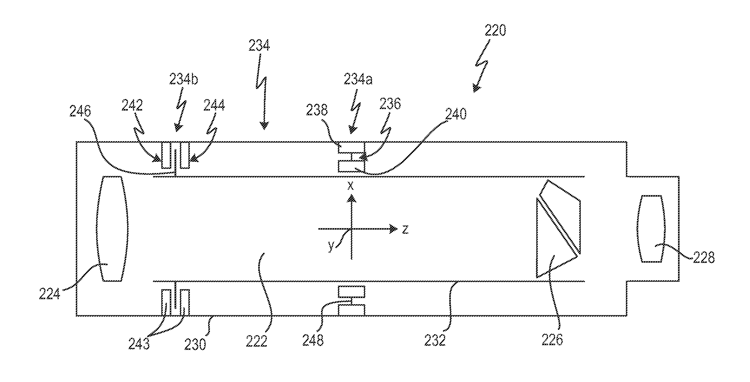
[0073]With reference to FIG. 4, firstly a long-range optical device will be described, as is known in the prior art and which is used as a starting point for refinements according to the invention, which will be described later with reference to FIGS. 9 to 15.

[0074]The long-range optical device shown with the general reference number 220 has an optical channel 222, in which an arrangement of optical elements 224, 226, and 228 is arranged. The optical elements 224, 226, and 228 are shown in simplified form here, wherein the optical element 224 forms the objective, the optical element 228 forms the eyepiece, and the optical element 226 forms the image inversion system of the long-range optical device 220. In the case in which the long-range optical device 220 is a binocular telescope, in particular a pair of binoculars, it accordingly has two optical channels 222, of which only the one channel is shown here.

[0075]The optical channel 222 has a housing 230, in which the arrangement of t...


PUM


Abstract

A long-range optical device has at least one optical channel, which has a housing and an arrangement of optical elements, wherein at least one of the optical elements is movable relative to the housing for image stabilization in the event of perturbing movements of the housing. The device further has a first passive stabilization system based on mass inertia for the at least one movable optical element, which, in the event of displacement of the at least one optical element relative to the housing, generates a first restoring force proportional to the displacement and a second restoring force proportional to the displacement velocity. The first stabilization system is designed for image stabilization in the event of perturbing movements in a first frequency range. The long-range optical device has at least one second stabilization system, which is coupled to the first stabilization system and is designed for image stabilization against perturbing movements in at least one second frequency range, wherein the first and the at least one second frequency ranges are at least partially different.

Description

CROSS REFERENCES TO RELATED APPLICATIONS[0001]This application is a continuation of international patent application PCT / EP2013 / 050175, filed on Jan. 8, 2013 designating the U.S., which international patent application has been published in German language and claims priority from German patent application No. 10 2012 000857.0, filed on Jan. 13, 2012, and from U.S. provisional patent application No. 61 / 586,321, filed on Jan. 13, 2012. The entire contents of these priority applications are incorporated herein by reference.BACKGROUND OF THE INVENTION[0002]The invention relates to long-range optical devices. A long-range optical device can be a monocular or binocular telescope in the meaning of the present invention, in particular a pair of binoculars. In the case of a binocular telescope, the long-range optical device has two optical channels.[0003]During the usage of a long-range optical device, for example, a pair of binoculars, perturbing movements of the housing of the long-range ...

Claims


Application Information

Patent Timeline
IPC IPC(8): G02B27/64G02B23/18
CPCG02B23/18G02B27/646G02B23/02G02B27/644
Inventor BECKER, KURTBACH, CHRISTIANGUENTHER, GEORGDOBERMANN, DIRK
Owner CARL ZEISS SMT GMBH
Why Eureka
Try Eureka