Implementing Multicast Link Trace Connectivity Fault Management in an Ethernet Network

a multicast link and fault management technology, applied in the field of ethernet networks, can solve the problems of large number of extraneous ltr messages, over-utilization of links, and non-utilization of links that weren't part of the spanning tr

Active Publication Date: 2014-12-18
EXTREME NETWORKS INC
View PDF7 Cites 8 Cited by
  • Summary
  • Abstract
  • Description
  • Claims
  • Application Information

AI Technical Summary

Benefits of technology

[0019]Multicast link trace Connectivity Fault Management (CFM) is implemented in an Ethernet network by causing nodes on the network which perform Reverse Path Forwarding Check (RPFC) based on packet Source Address (SA) to not update the packet SA when updating the content of the CFM message. Alternatively multicast CFM is implemented by causing nodes on the network to update the packet SA when the content of the CFM message is updated, but cause a secondary RPFC process to be implemented by a control process in connection with processing the CFM message. The secondary RPFC process is based on a combination of source and content contained in the payload of the CFM message.

Problems solved by technology

However the spanning tree itself was restrictive and often led to over-utilization of the links that were on the spanning tree and non-utilization of the links that weren't part of the spanning tree.
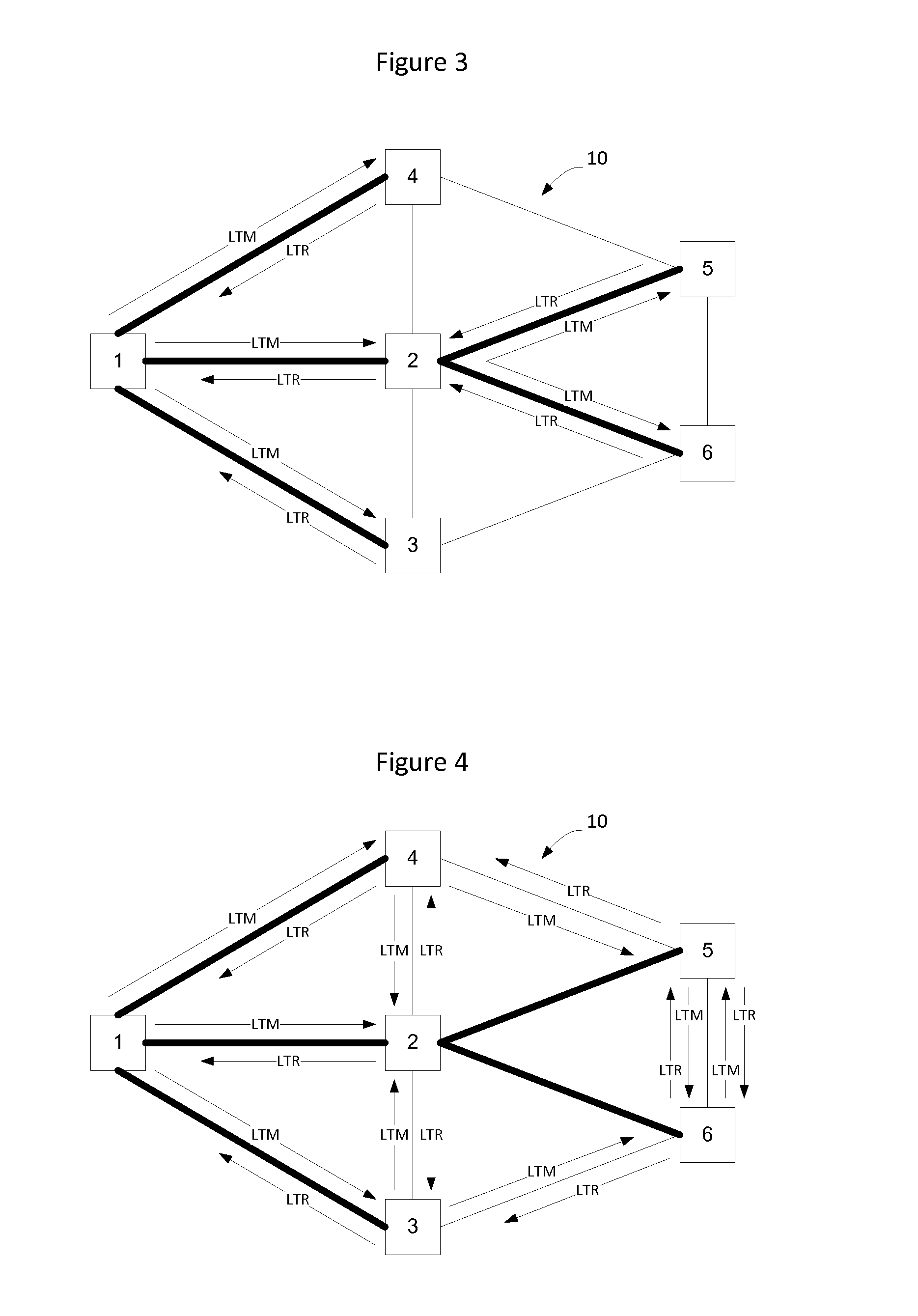
As shown in FIG. 4, this results in the generation of a large number of extraneous LTR messages.
However, not all nodes are able to implement RPFC using the multicast destination MAC address.
Unfortunately, in connection with link trace packets, each node that processes the link trace message will update the payload field of the link trace message to add information indicating that the message was relayed by the node.
Hence, nodes that implement RPFC based on the source address will not squelch erroneous transmission of link trace messages, which results in an inability to properly trace a multicast tree through the network.

Method used


Image

  • Implementing Multicast Link Trace Connectivity Fault Management in an Ethernet Network
  • Implementing Multicast Link Trace Connectivity Fault Management in an Ethernet Network
  • Implementing Multicast Link Trace Connectivity Fault Management in an Ethernet Network

Examples


Embodiment Construction

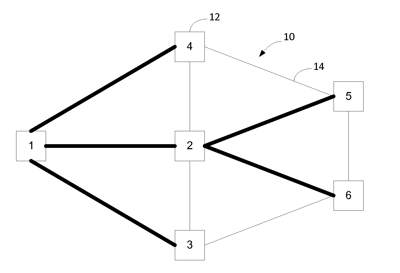
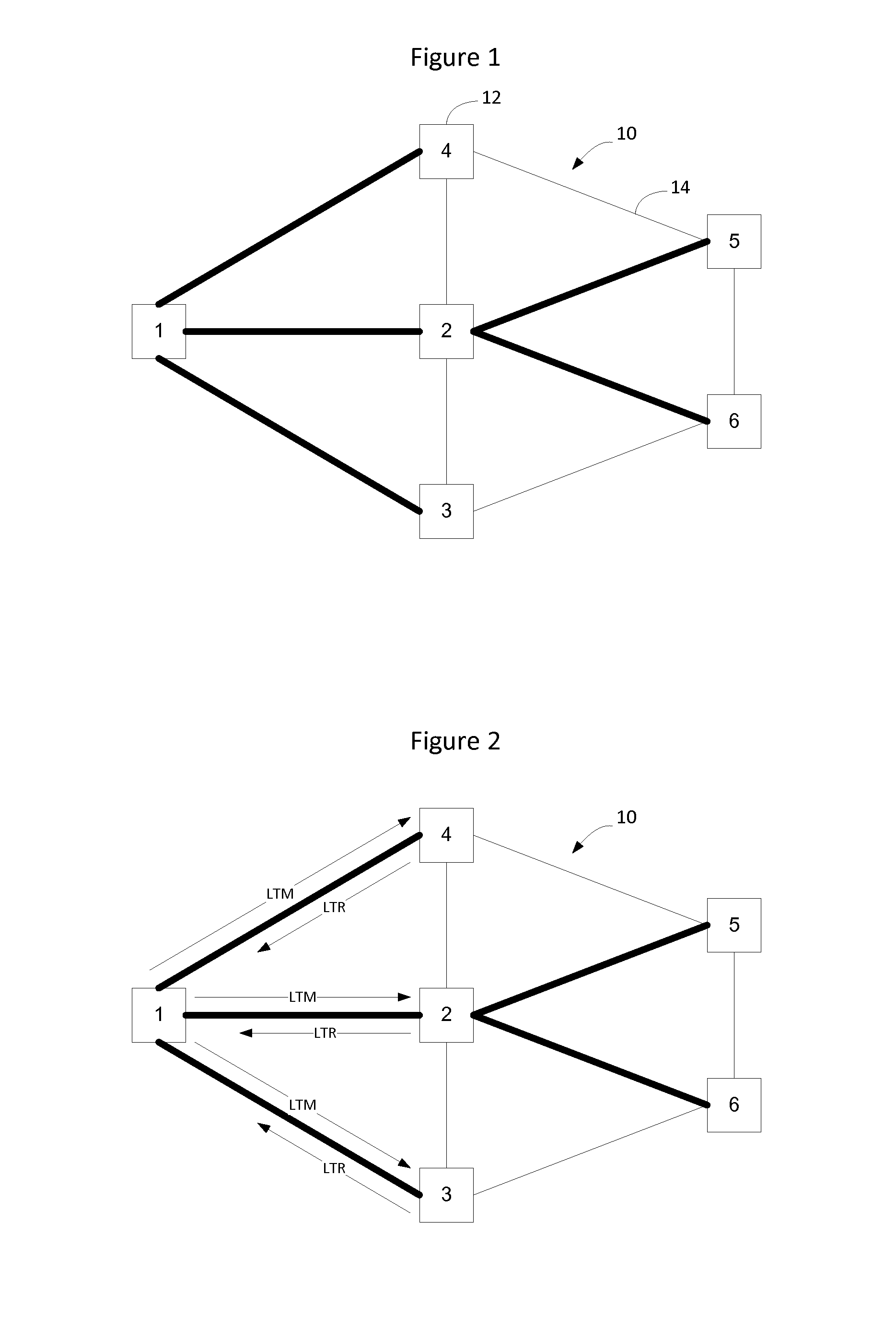
[0027]Nodes on a link state protocol controlled Ethernet network implement a link state routing protocol such as Intermediate System to Intermediate System (IS-IS). The nodes on the network learn adjacencies from the IS-IS Link State Advertisements (LSAs), also known as Link 913016-US-NP State Packets, and compute shortest paths between all pairs of nodes on the network. Each participating node populates its Forwarding Information Base (FIB) to construct unicast forwarding state between each pair of nodes on the network. Traffic engineered paths may also be constructed and forwarding state for the TE paths is installed into the nodes' FIBs on the network.

[0028]IS-IS permits topology information and the bindings of layer 2 and layer 3 addresses to specific network locations and interfaces to be exchanged independent of the switching or forwarding technology used in specific network elements. This facilitates two things, the first is that the topology considered by the IS-IS computati...


PUM


Abstract

Multicast link trace Connectivity Fault Management (CFM) is implemented in an Ethernet network by causing nodes on the network which perform Reverse Path Forwarding Check (RPFC) based on packet Source Address (SA) to not update the packet SA when updating the content of the CFM message. Alternatively multicast CFM is implemented by causing nodes on the network to update the packet SA when the content of the CFM message is updated, but cause a secondary RPFC process to be implemented by a control process in connection with processing the CFM message. The secondary RPFC process is based on a combination of source and content contained in the payload of the CFM message.

Description

CROSS-REFERENCE TO RELATED APPLICATIONS[0001]None.TECHNICAL FIELD[0002]The present invention relates to Ethernet networks and, more particularly, to implementing multicast link trace connectivity fault management in an Ethernet network.BACKGROUND[0003]Data communication networks may include various computers, servers, nodes, routers, switches, bridges, hubs, proxies, and other network devices coupled to and configured to pass data to one another. These devices will be referred to herein as “network elements.” Data is communicated through the data communication network by passing protocol data units, such as Internet Protocol packets, Ethernet Frames, data cells, segments, or other logical associations of bits / bytes of data, between the network elements by utilizing one or more communication links between the network elements. A particular protocol data unit may be handled by multiple network elements and cross multiple communication links as it travels between its source and its des...

Claims


Application Information

Patent Timeline
Patent Type & Authority Applications(United States)
IPC IPC(8): H04L12/24
CPCH04L41/0654H04L43/10H04L43/0811
Inventor KEESARA, SRIKANTHFITZGERALD, DEBORAH ELLEN
Owner EXTREME NETWORKS INC
Why Eureka
Try Eureka