
Embedding method

a technology of embossed and molded parts, applied in the field of embossed methods, can solve the problems of improper and the placement of the structure b>730

Active Publication Date: 2014-12-18
VERILY LIFE SCI LLC
View PDF1 Cites 11 Cited by
  • Summary
  • Abstract
  • Description
  • Claims
  • Application Information

AI Technical Summary

Benefits of technology

The invention is about a body-mountable device that can be worn on the body to detect analytes. The device consists of a transparent plastic layer with a structure embedded inside it that has a sensor and antenna. The structure is positioned on the first layer and is conformed to its shape. The first layer is made of a curved polymer that defines the posterior side of the device. A second layer is then added to fully enclose the structure and define the anterior side of the device. This technology allows for the creation of a wearable device that is unobtrusive and comfortable while still being effective in detecting analytes.

Problems solved by technology

However, in other examples, a plurality of conductive loops may not be a continuous material.
For instance, movement of the structure 730 during subsequent formation steps, such as formation of a second polymer layer, may result in improper placement of the structure 730 relative to the surrounding polymer layers.
As one example, movement of the structure 730 during filling a mold piece with a polymeric material to form the second polymer layer and / or curing the second polymer layer can result in improper placement of the structure 730 relative to the surrounding polymer layers.

Method used


Image

  • Embedding method
  • Embedding method
  • Embedding method

Examples


Embodiment Construction

[0022]The following detailed description describes various features and functions of the disclosed systems and methods with reference to the accompanying figures. In the figures, similar symbols typically identify similar components, unless context dictates otherwise. The illustrative system and method embodiments described herein are not meant to be limiting. It will be readily understood that certain aspects of the disclosed systems and methods can be arranged and combined in a wide variety of different configurations, all of which are contemplated herein.

I. INTRODUCTION

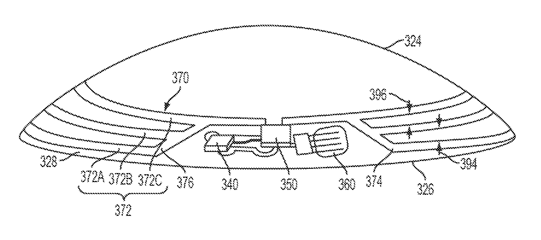
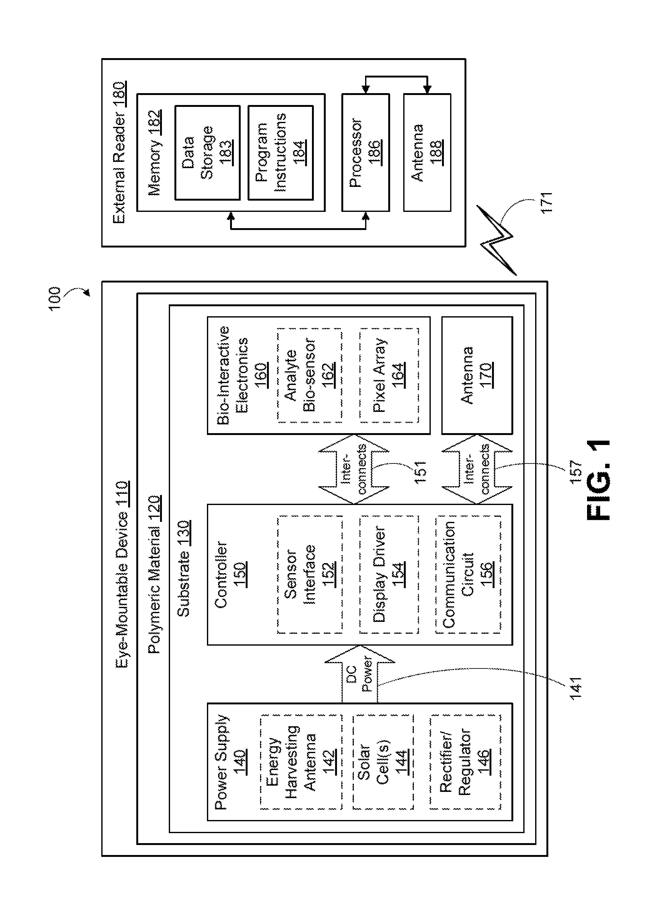
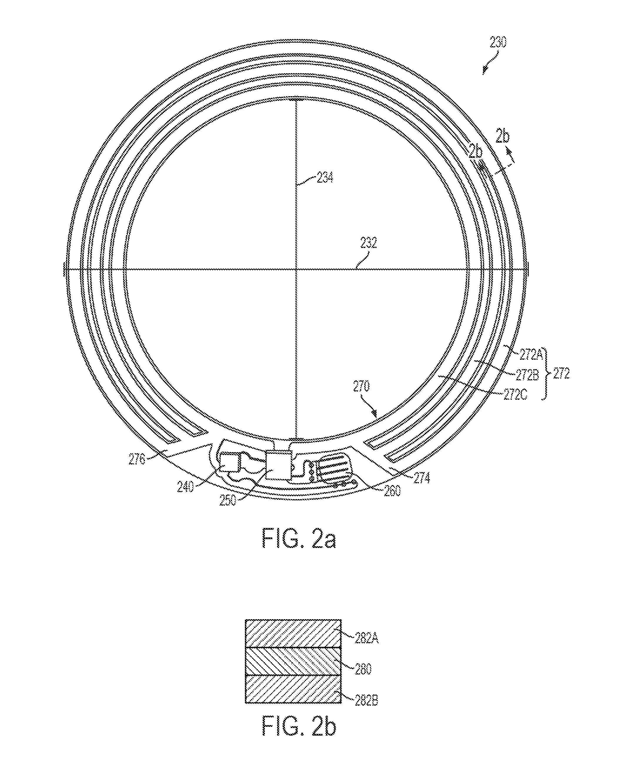
[0023]A body-mountable device may include a transparent polymer and a structure embedded in the transparent polymer that has an outer diameter and an inner diameter. The transparent polymer defines a posterior side and an anterior side of the body-mountable device. The structure includes a sensor configured to detect an analyte and an antenna that includes a plurality of conductive loops spaced apart from each othe...


PUM

PropertyMeasurementUnit
Diameteraaaaaaaaaa
Electrical conductoraaaaaaaaaa
Transparencyaaaaaaaaaa

Abstract

Body-mountable devices and methods for embedding a structure in a body-mountable device are described. A body-mountable device includes a transparent polymer and a structure embedded in the transparent polymer. The transparent polymer defines a posterior side and an anterior side of the body-mountable device. The structure has an outer diameter and an inner diameter and includes a sensor configured to detect an analyte and an antenna. The antenna includes a plurality of conductive loops spaced apart from each other between the outer diameter and the inner diameter.

Description

BACKGROUND[0001]Unless otherwise indicated herein, the materials described in this section are not prior art to the claims in this application and are not admitted to be prior art by inclusion in this section.[0002]A body-mountable device may be configured to monitor health-related information based on at least one analyte detected in a fluid of a user wearing the body-mountable device. For example, the body-mountable device may comprise an eye-mountable device that may be in the form of a contact lens that includes a sensor configured to detect the at least one analyte (e.g., glucose) in a tear film of a user wearing the eye-mountable device. The body-mountable device may also be configured to monitor various other types of health-related information.SUMMARY[0003]In one aspect, a body-mountable device is disclosed. An example body-mountable device includes: a transparent polymer, wherein the transparent polymer defines a posterior side and an anterior side of the body-mountable dev...

Claims


Application Information

Patent Timeline
IPC IPC(8): A61B5/00A61B5/1486A61B5/145
CPCA61B5/6821A61B5/682A61B5/1486A61B5/14532A61B5/002A61B2562/12G02C7/04Y10T156/1028
Inventor ETZKORN, JAMESO'DRISCOLL, STEPHEN
Owner VERILY LIFE SCI LLC
Learn More