Heat dissipating device and manufacturing method of heat dissipating device
- Summary
- Abstract
- Description
- Claims
- Application Information
AI Technical Summary
Benefits of technology
Problems solved by technology
Method used
Image

Examples
first embodiment
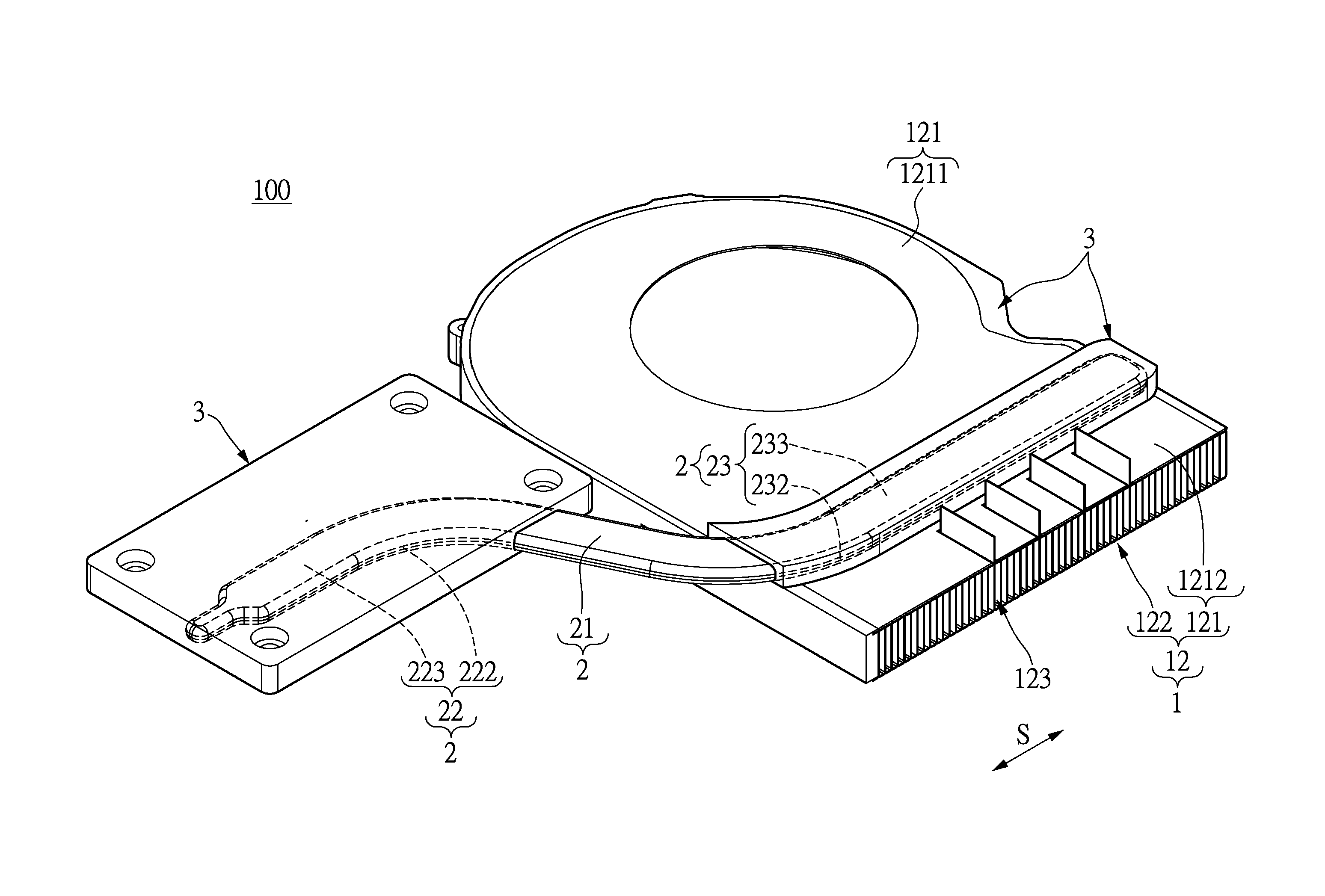
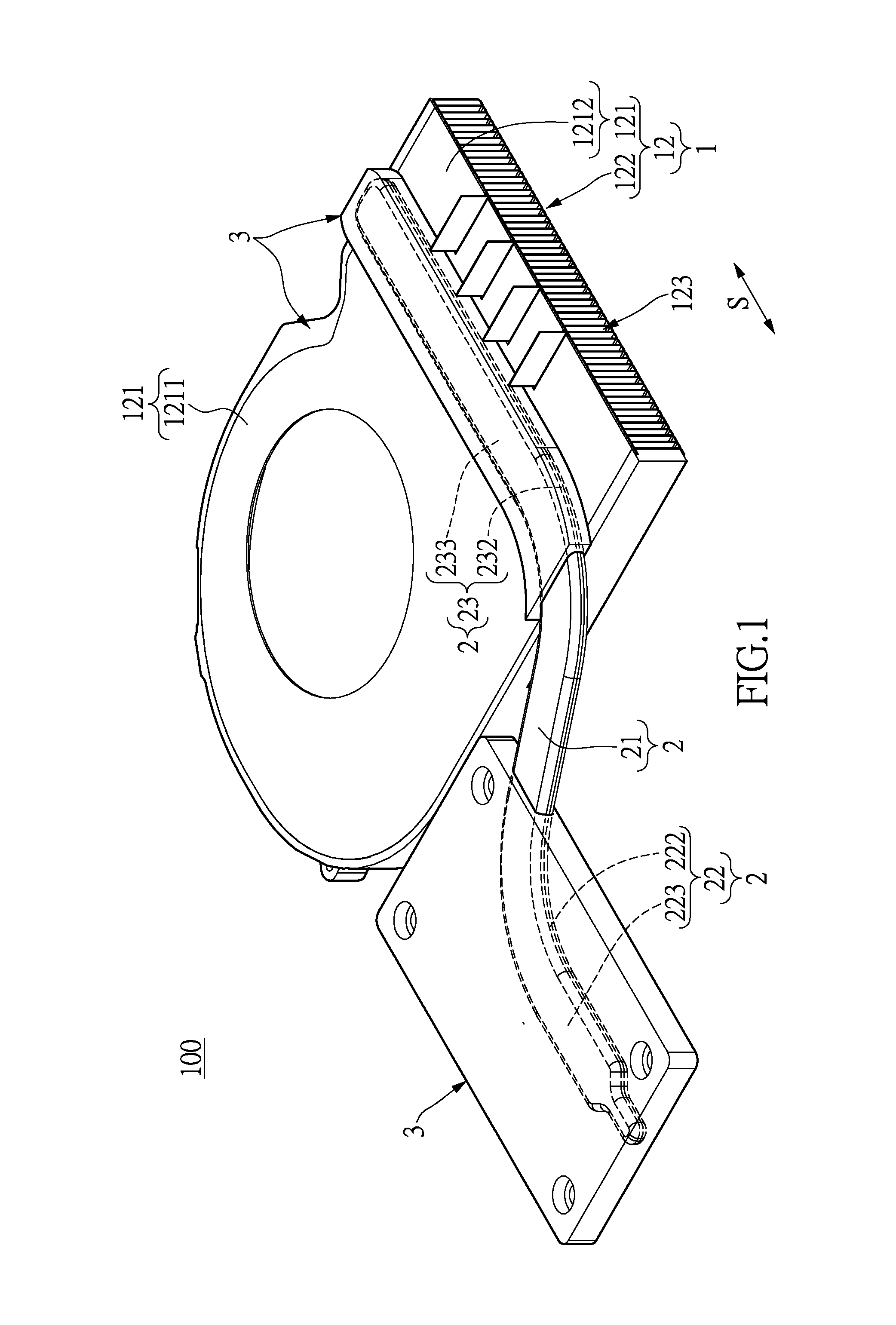
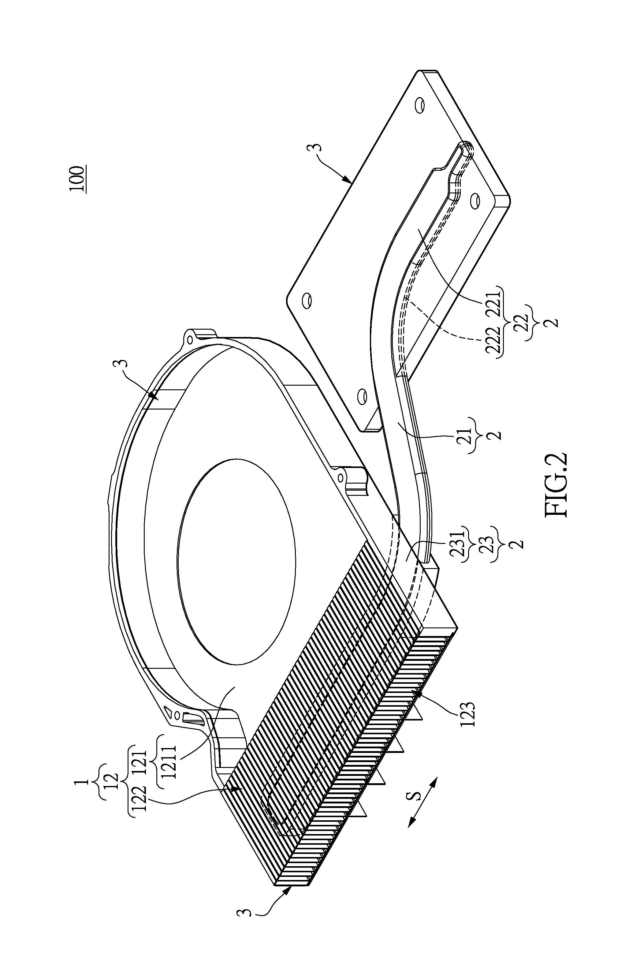
[0042]Please refer to FIGS. 1, 2, and 4. The injection molded member 3 is an integrally formed structure, and the contour of the injection molded member 3 is approximately a rectangular plate, so that the heat conductive set in the instant embodiment is formed without a fixing plate 112 and a heat conductive block 111 (as shown in FIG. 7). The inner surface of the injection molded member 3 is substantially and seamlessly connecting to the fixing surfaces 222 and the assisting surface 223 for establishing a firm connection between the injection molded member 3 and the heat input segment 22, and the arced design of the fixing surface 222 is further enhancing the above connection.
[0043]Moreover, the contact surface 221 of the heat input segment 22 exposes from the injection molded member 3 for abutting against a heat generating component (not shown). The contact surface 221 and the adjacent outer surface of the injection molded member 3 are preferably in coplanar arrangement, but are n...
second embodiment
[0044]Please refer to FIGS. 5 and 6. The heat dissipating module 1 includes a heat conductive unit 11, and the heat conductive unit 11 in the instant embodiment takes a sheet-like heat conductive block 111 for example. The heat conductive block 111 has a first surface 1111, a second surface 1112, and an annular lateral surface 1113. The first and second surfaces 1111, 1112 are two opposite surfaces of the heat conductive block 111, and the lateral surface 1113 connects an edge of the first surface 1111 and an edge of the second surface 1112. Specifically, the cross-section of the lateral surface 1113 of the heat conductive block 111 gradually reduces from the first surface 1111 to the second surface 1112. That is to say, the lateral surface 1113 is slantingly extended and tapered from the edge of the first surface 1111 to the edge of the second surface 1112.
[0045]The contact surface 221 of the heat input segment 22 is abutted against the first surface 1111 of the heat conductive blo...
third embodiment
[0047]Please refer to FIGS. 7 through 10. The heat dissipating module 1 includes a heat conductive unit 11, and the heat conductive unit 11 in the instant embodiment includes a sheet-like heat conductive block 111 and a fixing plate 112 for example. The heat conductive block 111 in the instant embodiment is identical to the heat conductive block 111 in the second embodiment, so that the instant embodiment does not state the construction of heat conductive block 111 again.
[0048]The fixing plate 112 includes an annular platy body 1121 and a retaining structure 1122 integrally extended from the platy body 1121. The platy body 1121 has an annular inner surface 1121a defining a space for accommodating the heat conductive block 111. The retaining structure 1122 includes two retaining sheets (not numbered), and the retaining sheets are respectively extended from two inside corners of the platy body 1121 toward each other for shielding part of the space surroundingly defined by the annular ...
PUM
| Property | Measurement | Unit |
|---|---|---|
| Electrical conductor | aaaaa | aaaaa |
Abstract
Description
Claims
Application Information
 - R&D
- Intellectual Property
- Life Sciences
- Materials
- Tech Scout
- Unparalleled Data Quality
- Higher Quality Content
- 60% Fewer Hallucinations
Browse by: Latest US Patents, China's latest patents, Technical Efficacy Thesaurus, Application Domain, Technology Topic, Popular Technical Reports.
© 2025 PatSnap. All rights reserved.Legal|Privacy policy|Modern Slavery Act Transparency Statement|Sitemap|About US| Contact US: help@patsnap.com