
Tripod head

Inactive Publication Date: 2015-01-01
VOGT PHILIPPE
View PDF5 Cites 7 Cited by
  • Summary
  • Abstract
  • Description
  • Claims
  • Application Information

AI Technical Summary

Benefits of technology

[0010]An object of the present invention is to provide a tripod head which has greater adjustment opt

Problems solved by technology

Moreover, the cavity can be used in a space-saving manner as an installation space, thus making the entire tripod head smaller and lightweight.

Method used


Image

  • Tripod head
  • Tripod head
  • Tripod head

Examples


Example

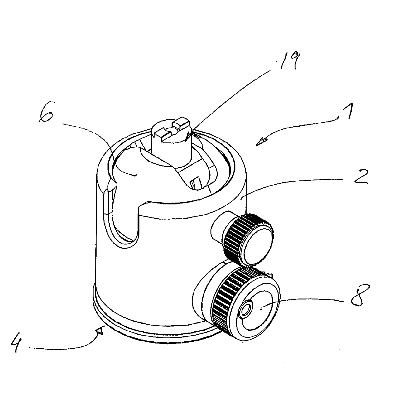
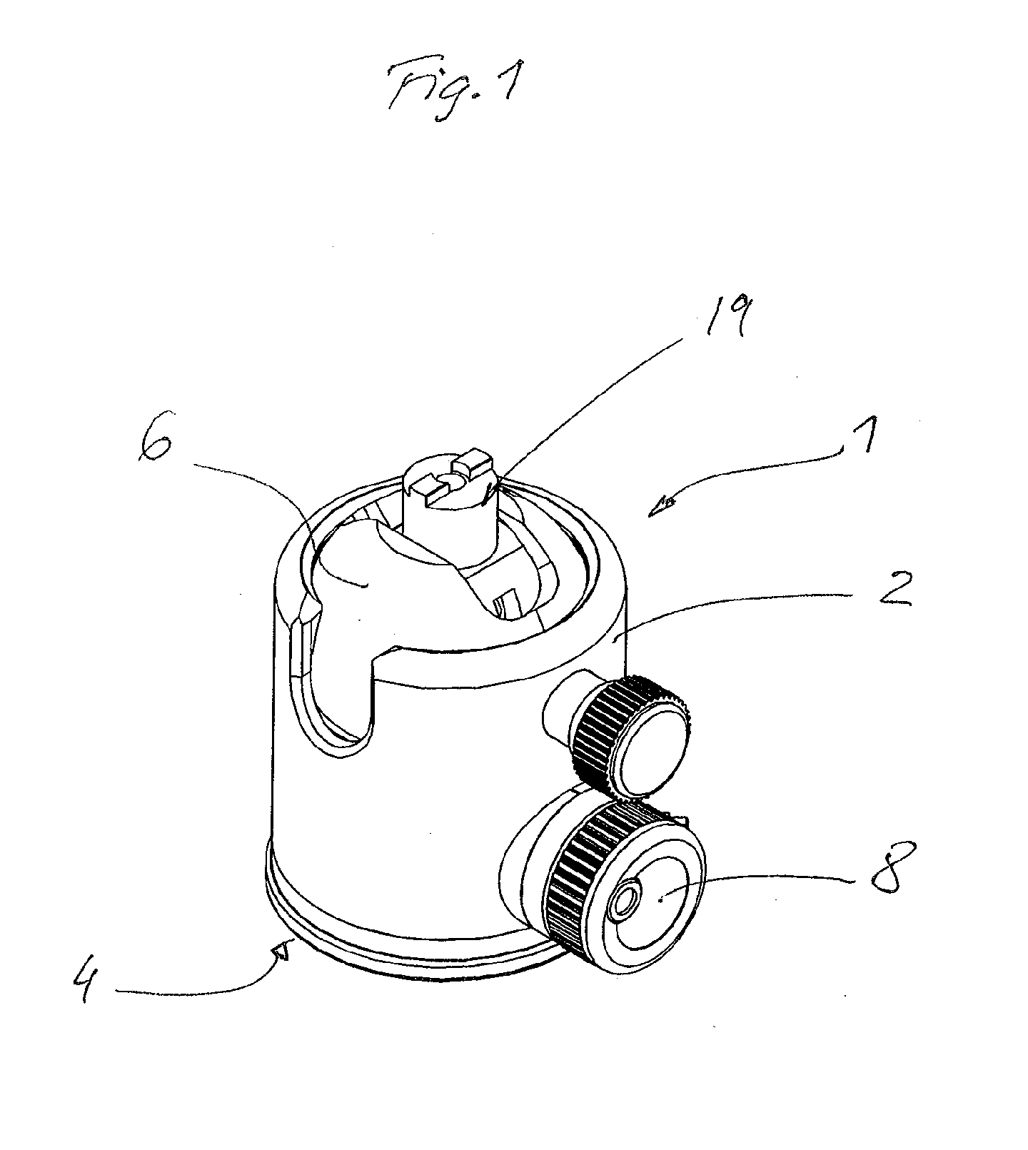
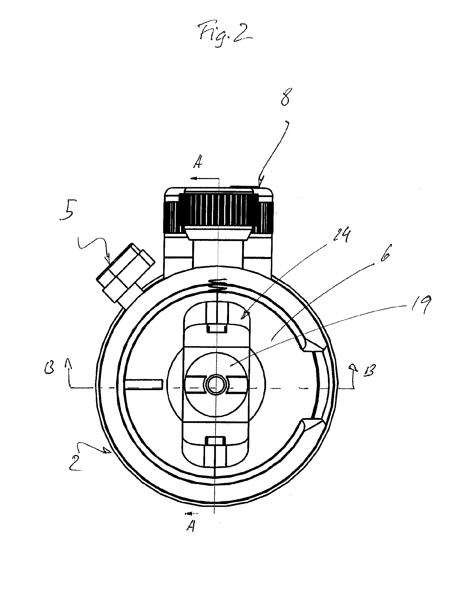
[0026]The figures illustrate a tripod head, designated in its entirety by the reference numeral 1, for a camera.

[0027]The tripod head comprises a cylindrical housing 2 which is mounted on a panoramic turntable 4 by means of a sliding bearing 3.

[0028]A threaded bore for fastening to a tripod is provided in the turntable 4.

[0029]The panoramic turntable 4 can be locked or released by means of an adjusting knob 5.

[0030]Also provided in the housing 2 is a pivotable joint ball 6 which can be clamped against the housing 2 for fixing purposes by means of a locking device 7. The locking device 7 is actuated by means of a rotary knob 8 which is arranged externally on the housing periphery.

[0031]The locking device 7 comprises a threaded spindle 9 which is actuated by means of the rotary knob 8 and on which two threaded blocks 10 are arranged which each comprise an outwardly directed inclined surface 11. Resting on the inclined surfaces 11 is a ring 12 which is likewise configured with a corres...


PUM


Abstract

A tripod head for receiving an optical device, comprising a cylinder-shaped housing having a connection device for a tripod at one end, and comprising a plane-symmetrical body arranged such that it can pivot in the housing, and comprising a locking device for clamping the plane-symmetrical body, wherein the plane-symmetrical body is a hollow and two-piece joint ball, the cavity of which forms an installation space and a guide for a pivoting part.

Description

CROSS REFERENCE TO RELATED APPLICATION[0001]The present application claims the priority benefits of International Patent Application No. PCT / EP2013 / 052228, filed on Feb. 5, 2013, and claims benefit of DE 10 2012 101 007.2, filed on Feb. 8, 2012.BACKGROUND OF THE INVENTION[0002]The invention relates to a tripod head for receiving an optical device, comprising a cylinder-shaped housing which comprises a connection device for a tripod at one end, and comprising a plane-symmetrical body arranged such that it can pivot in the housing, and comprising a locking device for clamping the plane-symmetrical body.[0003]EP 1 473 510 A1 discloses a tripod head containing a cylindrical housing which comprises a connection means for a tripod at one end. It contains a joint ball which is mounted such that it can rotate and pivot in the housing, a receiving part for the joint ball and a device for locking the joint ball having at least one locking member and an adjusting screw, which device presses th...

Claims


Application Information

Patent Timeline
IPC IPC(8): F16M11/14F16M11/10
CPCF16M11/10F16M11/14F16M2200/022F16C11/106
Inventor VOGT, PHILIPPE
Owner VOGT PHILIPPE
Learn More