Inkjet printing apparatus and inkjet printing method

Active Publication Date: 2015-01-01
CANON KK
View PDF3 Cites 5 Cited by
  • Summary
  • Abstract
  • Description
  • Claims
  • Application Information

AI Technical Summary

Benefits of technology

[0006]An object of the present invention is to provide an inkjet printing apparatus and a printing method therefor which can change the co

Problems solved by technology

Accordingly, it is necessary to provide print heads having a specific nozzle arrangement and specialize a printing operation including a scan with the print heads and conveyance of a

Method used


Image

  • Inkjet printing apparatus and inkjet printing method
  • Inkjet printing apparatus and inkjet printing method
  • Inkjet printing apparatus and inkjet printing method

Examples


Example

First Embodiment

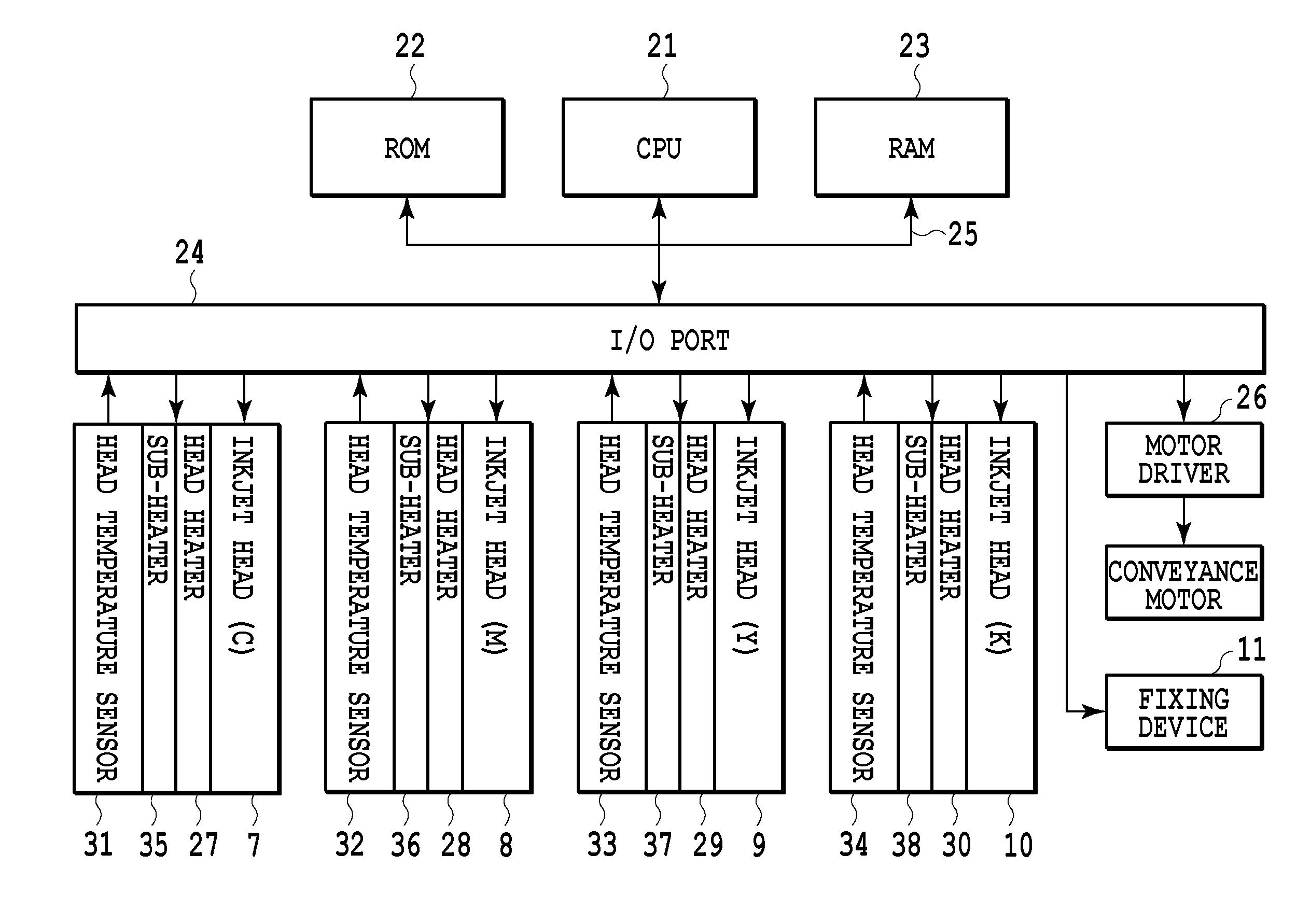
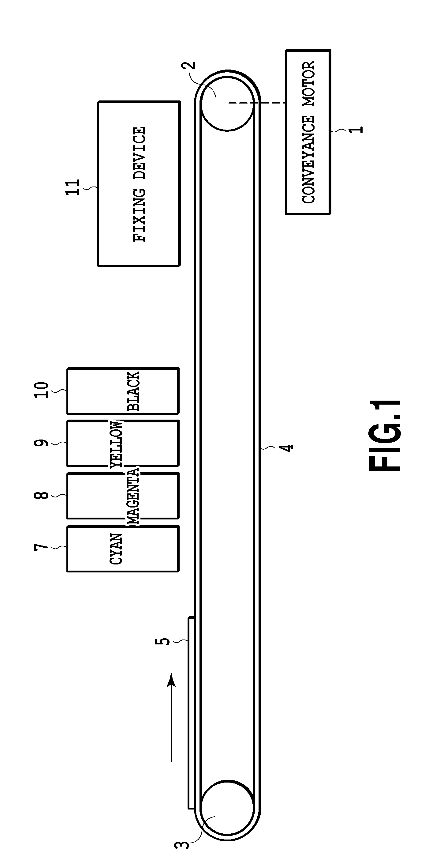
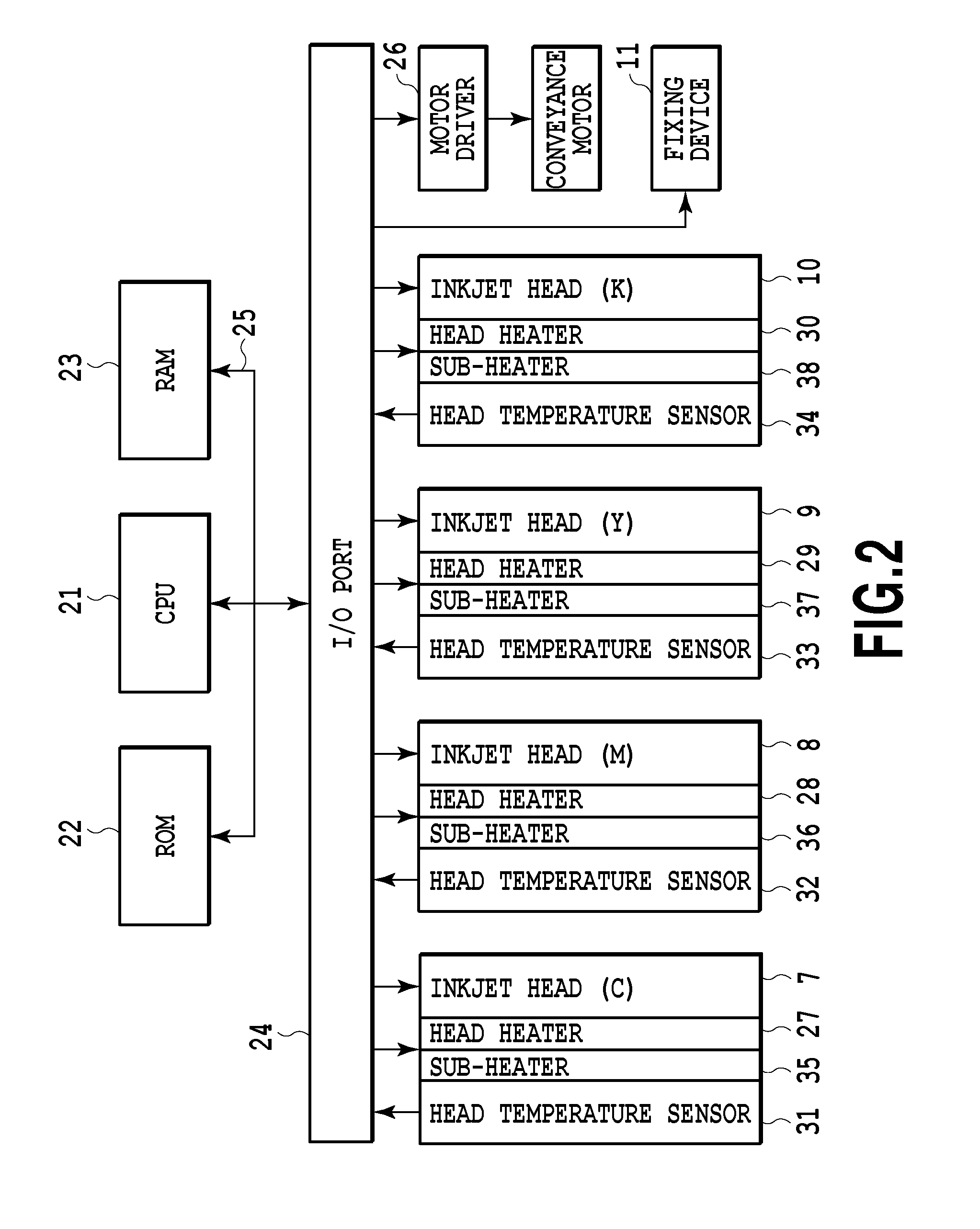
[0023]FIG. 1 is a diagram showing the schematic configuration of an inkjet printing apparatus according to an embodiment of the present invention as seen from a side. As shown in FIG. 1, the printing apparatus of the present embodiment is a so-called full-line type printing apparatus, and print heads 7, 8, 9, and 10 for cyan (C), magenta (M), yellow (Y), and black (K) inks are arranged along a conveyance direction of a print medium. A print medium 5 is conveyed relative to these print heads whose positions are fixed. In the present embodiment, a distance between these print heads is 0.02 [m]. The above inkjet printing apparatus of the embodiment can print an image on one surface of the print medium by only passing one time the print medium below each print head.

[0024]A belt 4 is suspended between a driven roller 2 rotated by the driving force of a conveyance motor 1 and a driven roller 3 placed away from the roller 2, whereby the belt 4 runs. The print medium 5 such ...

Example

Example 1

Case where the Diameter of the Preceding Ink and the Diameter of the Subsequent Ink are the Same

[0067]In Example 1, evaporation in a micro area can be ignored, and permeation of the preceding cyan and the subsequent magenta realizes a color whose color reproduction area is not distorted.

[0068]FIG. 9C shows a permeation area in which the preceding ink permeates and a state in which the subsequent ink lands (is ejected) in Example 1. In this example, a feedback temperature control is performed using the sub-heater 35 based on a temperature read from the temperature sensor 31 so that the temperature Tc of the preceding cyan ink ejected from the print head 7 becomes 41 [° C.]. With this control of increasing the ink temperature, the volume Vc of a permeation area 121 is two times as large as that of the permeation area 117 in a case where Tc=25 [° C.] (FIG. 8A) and the capillary occupancy rate Pc by the ink in the sheet is 50%.

[0069]In the permeation state shown in FIG. 9C, the...

Example

Example 2

Case where the Diameter of the Preceding Ink is Larger than the Diameter of the Subsequent Ink

[0072]In Example 2, a final permeation area of a sheet includes a permeation area in which only the preceding cyan permeates as well as an area in which the preceding cyan and the subsequent magenta exist in a mixed state to realize permeation states.

[0073]A feedback temperature control is performed by using the sub-heater 35 based on a temperature read from the temperature sensor 31 so that the temperature Tc of the preceding cyan ink ejected from the print head 7 becomes 60 [° C.]. With this control of increasing the ink temperature is increased, as shown in FIG. 9E, the volume Vc of a permeation area 123 is 2.75 times as large as the volume of the permeation area 117 obtained in a condition in which Tc=25 [° C.] and the capillary occupancy rate Pc by the ink is 36%. The permeation depth 1 of the permeation area 123 in which the preceding cyan permeates, the permeation area being...


PUM


Abstract

In an inkjet printing apparatus, the colors of ink dots are controlled to make it possible to change the colors of an image to be printed. More specifically, ink temperatures, ink permeation speeds, and the capillary occupancy rates of inks in a print medium are used to control a permeation area formed by performing printing with preceding cyan and subsequent magenta, thereby controlling the colors realized by the inks which are ejected in an overlapping manner.

Description

BACKGROUND OF THE INVENTION[0001]1. Field of the Invention[0002]The present invention relates to an inkjet printing apparatus and a printing method therefor, and particularly relates to controlling the color of an ink dot to be printed with a plurality of types of inks in an overlapping manner.[0003]2. Description of the Related Art[0004]It is known that in an inkjet printing method, the color (color appearance) of a dot on a print medium which is printed with a plurality of color inks in an overlapping manner varies depending on the order in which these inks are ejected and an ejection time difference. Japanese Patent No. 4343481 discloses that nozzles for ejecting a plurality of color inks are placed at different positions in a conveyance direction of a print medium to have the same order in which the plurality of inks are ejected, and to keep constant an ejection time difference between the plurality of inks in any scan area. This can suppress a color difference.[0005]However, th...

Claims


Application Information

Patent Timeline
IPC IPC(8): B41J2/21
CPCB41J2/2103B41J2/04563B41J2/04581B41J2/04528B41J2/0458
Inventor TSUCHIYA, OKINORIIKEDA, TOHRUNAKATANI, AKIHIKOFUJITA, TAKASHIAKIBA, HIROMITSUSASAKI, TAKERU
Owner CANON KK
Why Eureka
Try Eureka