Vehicle

Active Publication Date: 2015-01-08
TOYOTA JIDOSHA KK
View PDF9 Cites 75 Cited by
  • Summary
  • Abstract
  • Description
  • Claims
  • Application Information

AI Technical Summary

Problems solved by technology

However, the shield member is determined on the basis of the shape of the power receiving portion, and a design of the shield member, focusing on a shielding function associated with the shape of the vehicle, is not performed.

Method used


Image

  • Vehicle
  • Vehicle
  • Vehicle

Examples


first embodiment

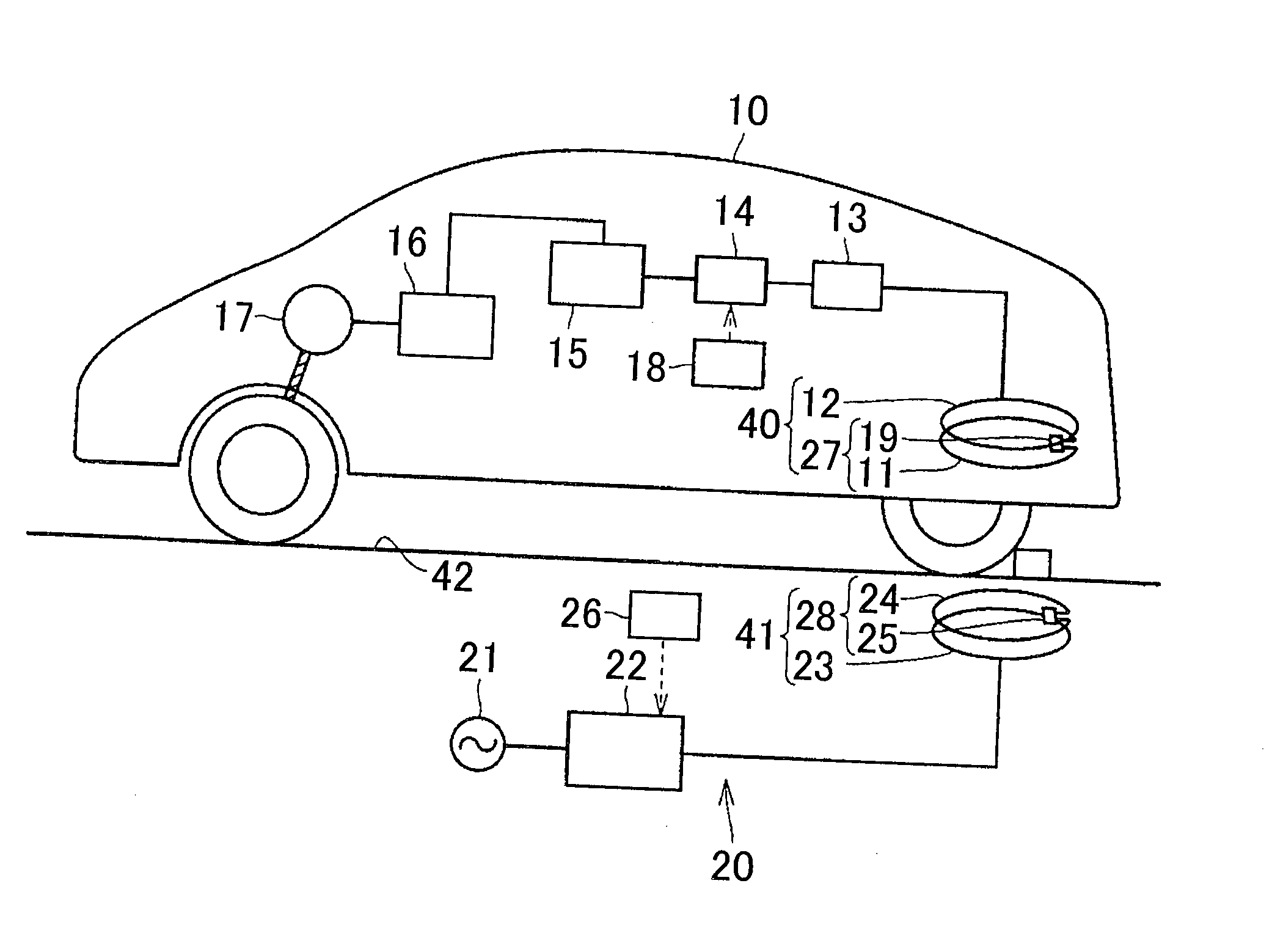
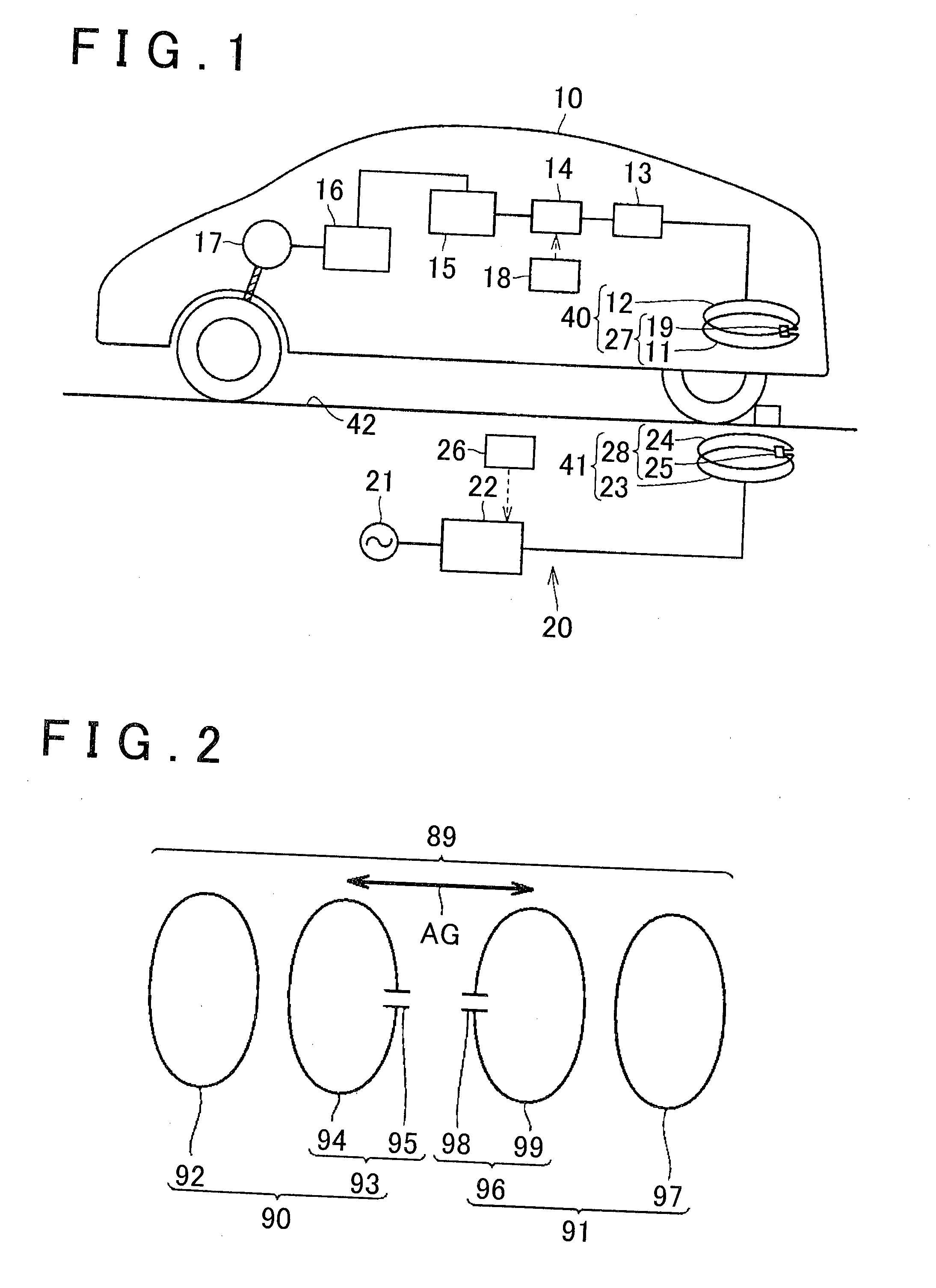
[0054]The power transfer system includes an electromotive vehicle 10 and an external power supply device 20. The electromotive vehicle 10 includes the power receiving device 40. The external power supply device 20 includes the power transmitting device 41. When the electromotive vehicle 10 is stopped at a predetermined position of a parking space 42 in which the power transmitting device 41 is provided, the power receiving device 40 of the electromotive vehicle 10 receives electric power from the power transmitting device 41.

[0055]A wheel block or a line that indicates a parking position and a parking area is provided in the parking space 42 so that the electromotive vehicle 10 is stopped at a predetermined position.

[0056]The external power supply device 20 includes a high-frequency power driver 22, a control unit 26 and the power transmitting device 41. The high-frequency power driver 22 is connected to an alternating-current power supply 21. The control unit 26 executes drive con...

second embodiment

[0123]As shown in FIG. 17, in the second embodiment, the shield member 400B includes a first shield region SR1 and a second shield region SR2 at a peripheral position that surrounds the power receiving portion 27. The first shield region SR1 has a high shielding function. The second shield region SR2 has a shielding function lower than that of the first shield region SR1.

[0124]The cylindrical portion 401 has a circular shape; whereas the shape of the flange portion 400f is formed in a substantially elliptical shape that is longer in the longitudinal direction than in the transverse direction (long side V21, short side H21). Furthermore, the cylindrical portion 401 is biased leftward, and the flange portion 400f on the right side of the cylindrical portion 401 is extended by a larger amount than the flange portion 400f on the left side of the cylindrical portion 401.

[0125]When the shield member 400B is partitioned by boundary lines BL21 and BL22 that respectively incline forward and ...

third embodiment

[0143]In this way, with the shield member 400C when the power receiving portion 27 is mounted on the electromotive vehicle 10, it is possible to mount the shield member 400C having a shielding function that reflects the shape of the under panel 10B that is the shape of the electromotive vehicle 10. As a result, it is possible to appropriately suppress the leakage electromagnetic field, and it is possible to reduce the weight and size of the shield member 400C by optimizing the shape of the shield member 400C.

[0144]FIG. 20 and FIG. 21 illustrate the case where the power receiving device 40 is mounted at the rear portion of the electromotive vehicle 10. Instead, when the power receiving device 40 is mounted at the front portion of the electromotive vehicle 10, the shield member 400C may be formed in a longitudinally symmetrical shape.

[0145]Next, the shape of the flange portion 400f of a shield member 400D according to a fourth embodiment will be described with reference to FIG. 22 an...


PUM

PropertyMeasurementUnit
electric poweraaaaaaaaaa
shielding functionaaaaaaaaaa
distanceaaaaaaaaaa

Abstract

A vehicle includes a power receiving portion that contactlessly receives electric power from a power transmitting portion provided outside the vehicle and includes a shield member that is arranged around the power receiving portion in the same plane as a plane in which the power receiving portion is arranged, wherein the shield member includes a first shield region having a high shielding function and a second shield region having a shielding function lower than that of the first shield region at a position around the power receiving portion.

Description

BACKGROUND OF THE INVENTION[0001]1. Field of the Invention[0002]The invention relates to a vehicle that includes a power receiving portion that uses a power transfer system.[0003]2. Description of Related Art[0004]In recent years, hybrid vehicles, electric vehicles, and the like, that drive drive wheels with the use of electric power from a battery, or the like, become a focus of attention in consideration of an environment.[0005]Particularly, in recent years, in the above-described electromotive vehicles equipped with a battery, wireless charging through which the battery is contactlessly chargeable without using a plug, or the like, becomes a focus of attention. Then, various contactless charging systems have been suggested recently.[0006]A power transfer system that uses a contactless charging system is, for example, described in Japanese Patent Application Publication No. 2011-072188 (JP 2011-072188 A) and Japanese Patent Application Publication No. 2011-045189 (JP 2011-045189 A...

Claims


Application Information

Patent Timeline
Patent Type & Authority Applications(United States)
IPC IPC(8): B60L11/18H01F38/14H01F27/36H01F27/28B60L5/00H05K9/00
CPCB60L11/182H01F27/36H01F38/14H01F27/2871H01F27/288Y02T90/14H04B5/0037B60L2270/147Y02T10/7072B60L53/126Y02T10/70H01F27/363H02J50/70H02J50/12H02J50/10Y02T90/12
Inventor ICHIKAWA, SHINJINAKAMURA, TORUISHIDA, MASAYAHATTORI, YOSHIYUKIWATANABE, TOSHIAKIKOJIMA, TAKASHI
Owner TOYOTA JIDOSHA KK
Why Eureka
Try Eureka