Eureka AIR delivers breakthrough ideas for toughest innovation challenges, trusted by R&D personnel around the world.

Resistive coupling for an automatic faucet

a technology of resistive coupling and automatic faucet, which is applied in the direction of valve operation/release device, mechanical apparatus, transportation and packaging, etc., can solve the problems of mechanically unreliable hands-free faucets,

Active Publication Date: 2015-01-15
DELTA FAUCET COMPANY
View PDF2 Cites 17 Cited by
  • Summary
  • Abstract
  • Description
  • Claims
  • Application Information

AI Technical Summary

Benefits of technology

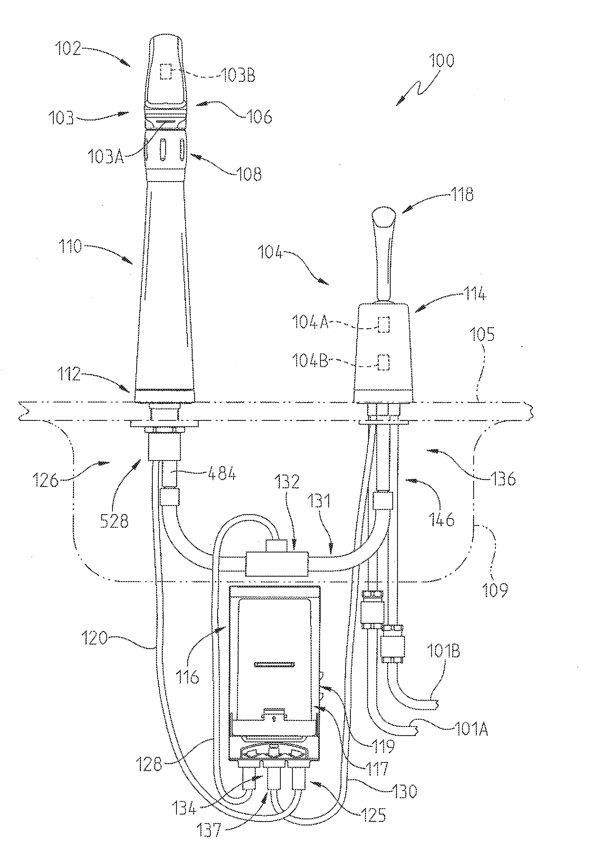
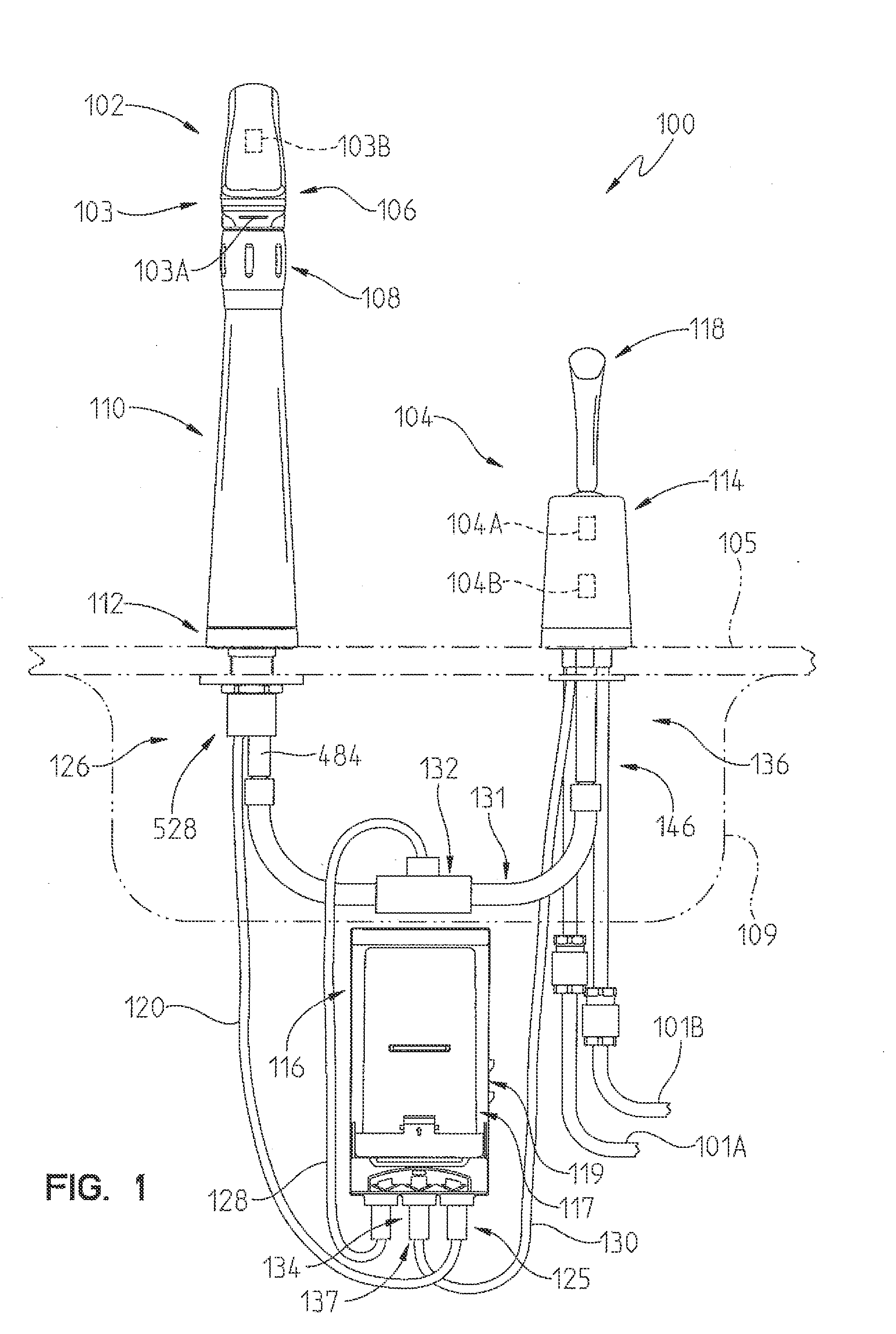
The present invention provides a kitchen faucet with a touch control for activating water flow through the faucet with a handle. The handle does not need to be moved to activate the faucet. Additionally, the invention retrofits a capacitive sensor onto existing faucets without impacting the design or requiring redesign of the faucet. The capacitive sensor works with single hole mount faucets, and can be easily installed or retrofitted.

Problems solved by technology

The former were unsatisfactory because a user could only wash one hand at a time, while the later proved to be mechanically unreliable.
For example, if the user wishes to fill the basin with water to wash something the hands-free faucet could be frustrating, since it would require the user to keep their hand continuously in the detection zone of the sensors.

Method used


Image

  • Resistive coupling for an automatic faucet
  • Resistive coupling for an automatic faucet
  • Resistive coupling for an automatic faucet

Examples


Embodiment Construction

[0054]For the purposes of promoting an understanding of the principles of the invention, reference will now be made to the preferred embodiment and specific language will be used to describe the same. It will nevertheless be understood that no limitation of the scope of the invention is thereby intended. Such alternations and further modifications in the invention, and such further applications of the principles of the invention as described herein as would normally occur to one skilled in the art to which the invention pertains, are contemplated, and desired to be protected.

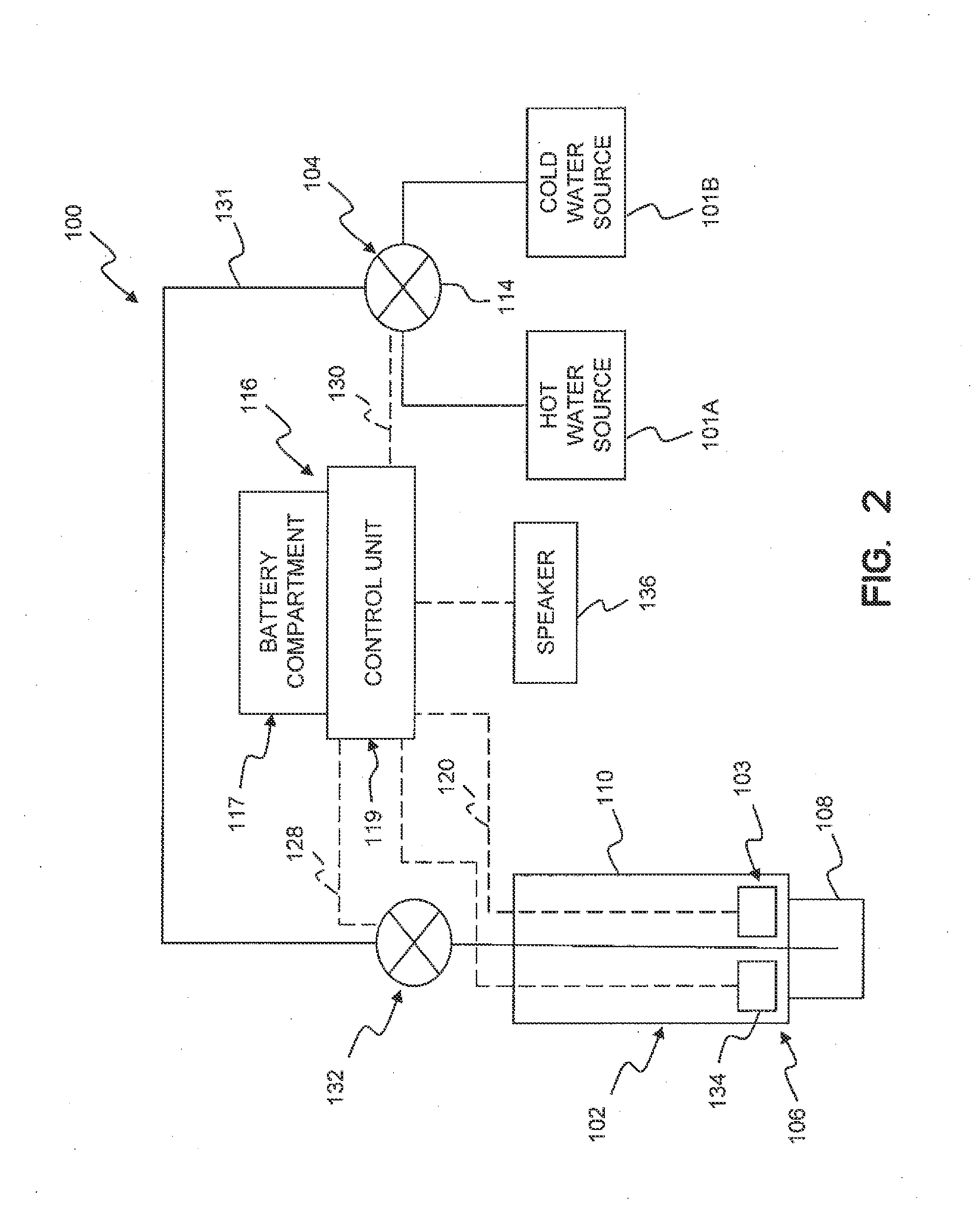
[0055]An illustrative embodiment of the present invention provides a kitchen-type faucet that can be placed in at least two modes, in order to provide water-efficient operation that is easy and convenient to use. In a hands-free mode, the water is activated and deactivated in response to a proximity sensor that detects when something is presently under the spout, so as to provide the most water-efficient operati...


PUM


Abstract

A faucet includes a logical control, a spout, a hub, a handle, and a touch control operably coupled to at least one of the spout, the hub, and the handle.

Description

CROSS-REFERENCE TO RELATED APPLICATIONS [0001]This application is a continuation-in-part of U.S. patent application Ser. No. 13 / 411,603, filed Mar. 4, 2012, now U.S. Pat. No. 8,844,564, which is a continuation of U.S. patent application Ser. No. 12 / 518,842, filed Jun. 11, 2009, now U.S. Pat. No. 8,127,782, which is a national phase filing of PCT International Application Ser. No. PCT / US2007 / 025336, filed Dec. 11, 2007, which is a continuation-in-part of U.S. patent application Ser. No. 11 / 641,574, filed Dec. 19, 2006, now U.S. Pat. No. 7,690,395, the disclosures of which are expressly incorporated herein by reference.BACKGROUND OF THE INVENTION[0002]1. Field of the Invention[0003]The present invention generally relates to the field of automatic faucets. More particularly, the present invention relates to an automatic faucet that uses both proximity and contact sensors in conjunction with logic that responds to various actions to provide easy and intuitive operation.[0004]2. Descript...

Claims


Application Information

Patent Timeline
Patent Type & Authority Applications(United States)
IPC IPC(8): E03C1/05H01C13/02H01C1/01
CPCH01C13/02E03C1/057H01C1/01E03C2001/0415H01C1/14Y10T137/9464
Inventor MARTY, GARRY R.SAWASKI, JOEL D.THOMAS, KURT J.DAVIDSON, KYLE R.
Owner DELTA FAUCET COMPANY
Why Eureka
Eureka Blog
Learn More