Beverage machine with carafe compatible drip tray

a beverage machine and compatible technology, applied in beverage vessels, domestic applications, kitchen equipment, etc., can solve the problems of likely overflowing beverage containers, not preventing machine operation, etc., to prevent beverage dispensing, convenient and easy-to-operate systems, and prevent beverage dispensing

Active Publication Date: 2015-01-15
KEURIG GREEN MOUNTAIN INC
View PDF3 Cites 16 Cited by
  • Summary
  • Abstract
  • Description
  • Claims
  • Application Information

AI Technical Summary

Benefits of technology

[0013]In another aspect of the invention, a beverage forming apparatus includes a drip tray assembly arranged to receive waste liquid at the carafe receiving area. The drip tray assembly may include one or more holes shaped and arranged to align with a periphery of a base of a carafe at the carafe receiving area and to receive liquid flowing down an outer surface of carafe to the carafe base. As a result, liquid that overflows the carafe and flows down the outer surface of the carafe may enter the one or more holes for receipt by a waste liquid receiving area. For example, the one or more holes may have an arcuate shape and collectively extend over an arc of 90 to 180 degrees. This may allow the holes to align with a circular periphery of the carafe base such that liquid flowing down the outer surface of the carafe may enter the holes. As noted above, liquid that overflows the carafe may spill over a spout of the carafe, and since the carafe may be positioned at the carafe receiving area at a wide range of angles, liquid may flow down the carafe sides across a relatively wide range of angles. By having the holes span a wide arc, e.g., 90 degrees or more, overflow liquid may be reliably collected at the holes.

Problems solved by technology

While the beverage machine may be controlled to dispense beverage only when a carafe lid is detected to be in the open position, there may be situations in which dispensed beverage is not actually received by the carafe.
For example, if a user places a partially full or full carafe at the carafe receiving area prior to beverage dispensing, the dispensed beverage will likely overflow the carafe because the carafe does not have sufficient volume to receive the beverage.
In such a case, it may be desirable to catch the waste liquid in a drip tray, but not prevent machine operation because of a small amount of expected dripping.

Method used


Image

  • Beverage machine with carafe compatible drip tray
  • Beverage machine with carafe compatible drip tray
  • Beverage machine with carafe compatible drip tray

Examples


Embodiment Construction

[0027]It should be understood that aspects of the invention are described herein with reference to certain illustrative embodiment and the figures. The illustrative embodiments described herein are not necessarily intended to show all aspects of the invention, but rather are used to describe a few illustrative embodiments. Thus, aspects of the invention are not intended to be construed narrowly in view of the illustrative embodiments. In addition, it should be understood that aspects of the invention may be used alone or in any suitable combination with other aspects of the invention.

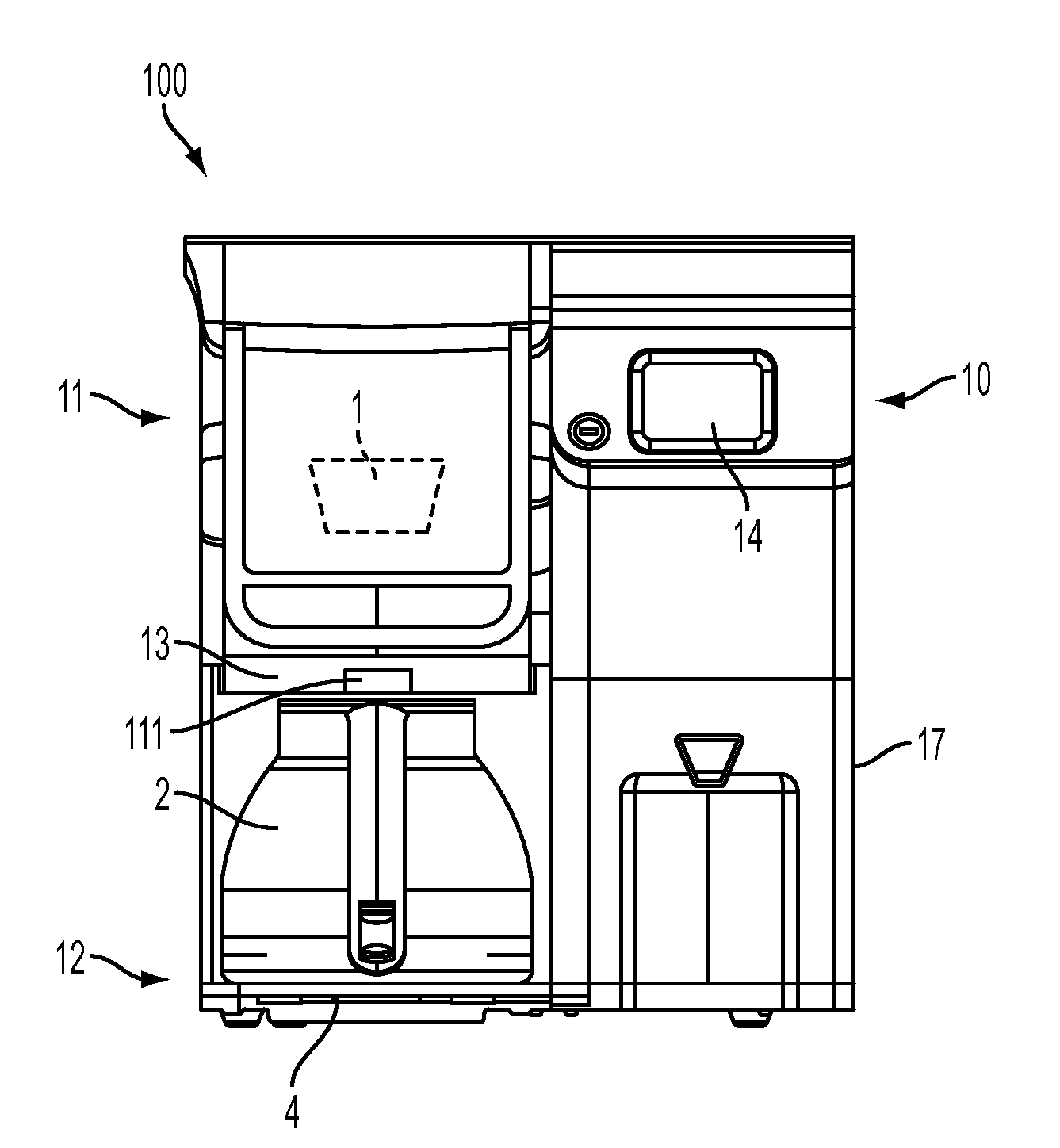
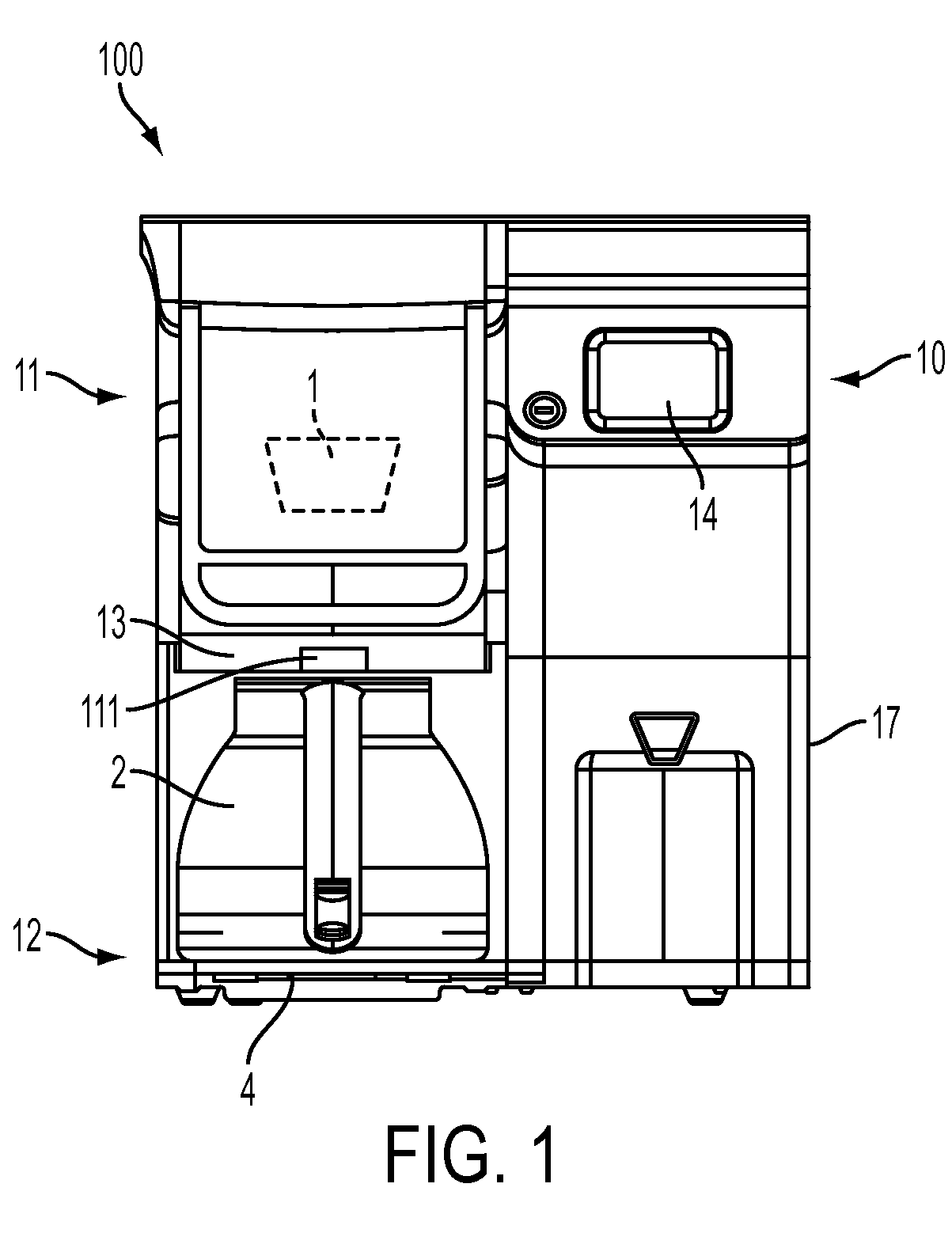
[0028]FIG. 1 shows a front view of a beverage forming apparatus 100 in an illustrative embodiment that incorporates aspects of the invention. Although the beverage forming apparatus 100 may be used to form any suitable beverage, such as tea, coffee, other infusion-type beverages, beverages formed from a liquid or powdered concentrate, soups, juices or other beverages made from dried materials, or other,...


PUM


Abstract

A beverage forming method and system in which a carafe is positionable at a carafe receiving area of a beverage forming machine with a lid of the carafe in an open position or a closed position. The carafe may be positioned at the carafe receiving area in any one of multiple rotational positions within a range of 45 to 180 degrees, and the machine may detect whether the lid is open or not for any of the rotational positions. A drip tray may receive waste liquid into two different waste liquid receiving areas, and may detect the presence of liquid for different volumes received into the respective areas. Holes or other opening in the drip tray may be configured to receive liquid flowing down a side surface of a carafe when the liquid reaches a periphery of the carafe base.

Description

CROSS REFERENCE TO RELATED APPLICATION[0001]This application claims the benefit of U.S. Provisional Application No. 61 / 844,691, filed Jul. 10, 2013, which is hereby incorporated by reference in its entirety.BACKGROUND[0002]1. Field of Invention This invention relates to beverage forming systems, such as coffee brewers that use a liquid to form a coffee beverage.[0003]2. Related Art[0004]Beverage forming systems that use a liquid, such as water, to form a beverage are well known. For example, U.S. Patent Application Publication 2011 / 0185907 discloses a coffee machine and receptacle that can be docked at a filling position on the machine to receive coffee made by the machine. The machine can detect the presence of the receptacle at the filling position, and starts an operating mode to produce coffee when the receptacle is at the filling position. However, the receptacle cannot be placed at the filling position unless a lid of the receptacle is oriented so that a recess in the lid is r...

Claims


Application Information

Patent Timeline
Patent Type & Authority Applications(United States)
IPC IPC(8): A47J31/46
CPCA47J31/46A47J31/4428A47J31/061
Inventor KASTOR, NIKOLAS
Owner KEURIG GREEN MOUNTAIN INC
Why Eureka
Try Eureka