Image forming apparatus

Inactive Publication Date: 2007-04-26
OKI DATA CORP
View PDF4 Cites 13 Cited by
  • Summary
  • Abstract
  • Description
  • Claims
  • Application Information

AI Technical Summary

Benefits of technology

[0006] An object of the invention is to solve the aforementioned drawbacks of the conventional apparatus and to provide an

Problems solved by technology

Providing a relatively large chamber for merely holding useless t

Method used


Image

  • Image forming apparatus
  • Image forming apparatus
  • Image forming apparatus

Examples


Example

First Embodiment

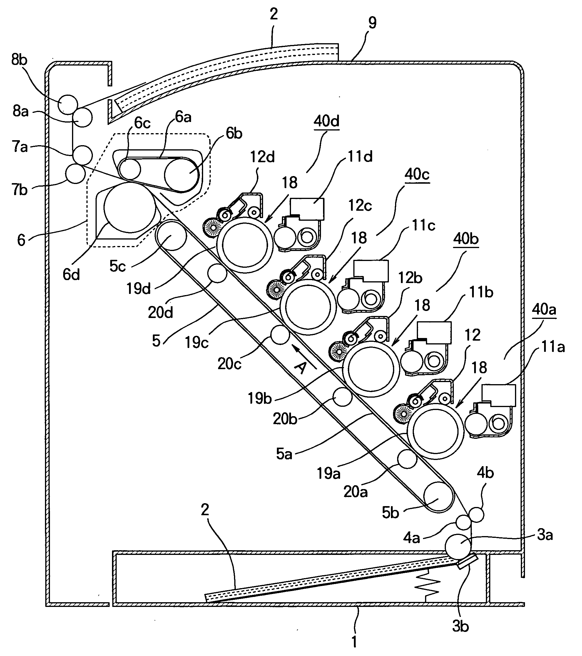
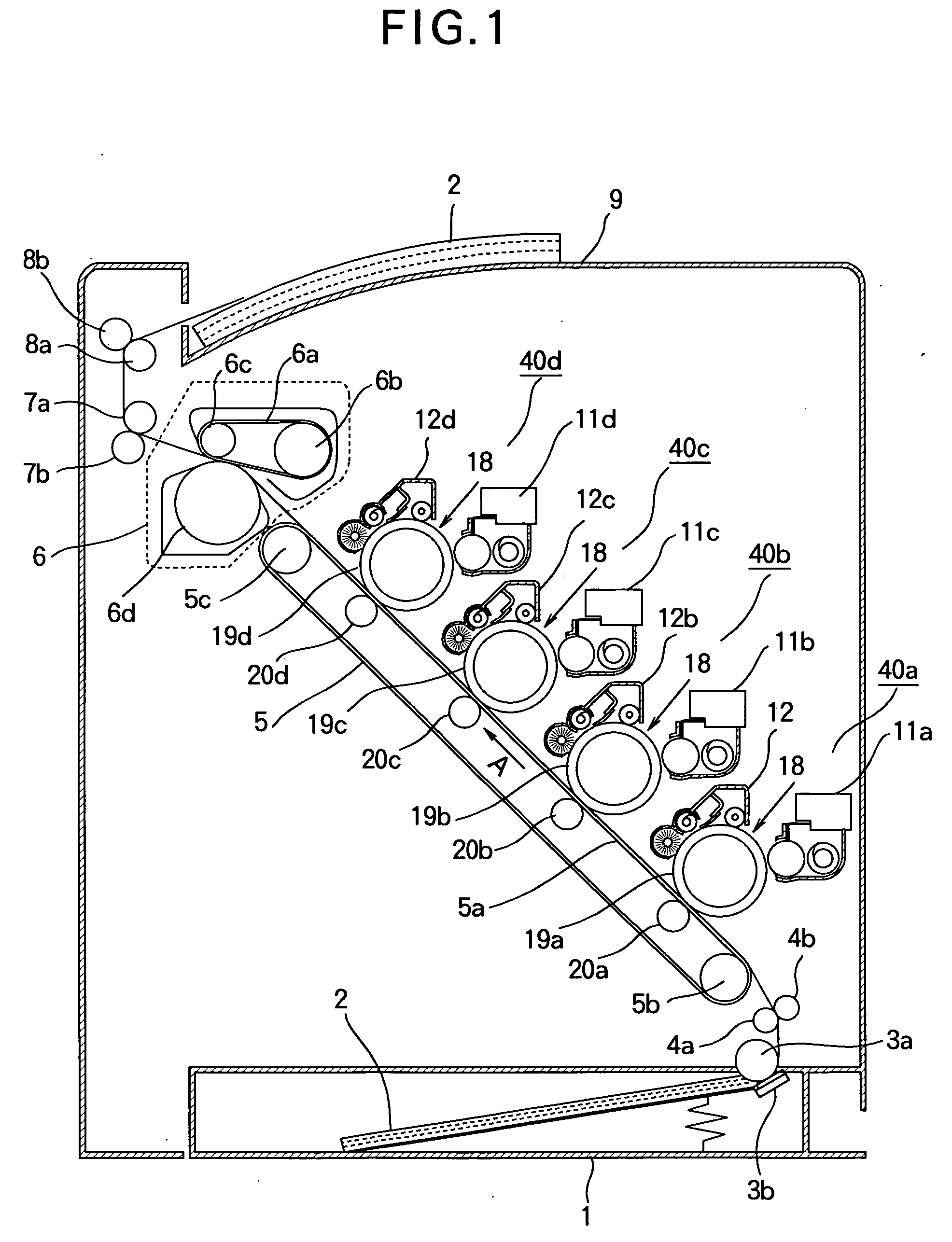
[0034]FIG. 1 illustrates an image forming apparatus according to the present invention. Image forming sections 40a-40d are aligned along a transfer belt 5a of a transfer unit 5, and form yellow, magenta, cyan, and black images, respectively. The image forming sections 40a-40d are aligned from a lower right corner to an upper left corner in such a way that the preceding one of adjacent ones is above the following one of the adjacent ones. The image forming sections 40a-40d include developing units 11a-11d and cleaning units 12a-12d, respectively. Developing rollers of the developing units 11a-11d are in pressure contact with the photoconductive bodies 19a-19d, respectively. The cleaning units 12a-12d abut the photoconductive bodies 19a-19d, respectively, to collect residual toner from the photoconductive bodies 19a-19d.

[0035] A medium tray 1 holds a stack of medium 2 therein. A separator roller 3a cooperates with a separator tongue 3b to separate a top page from the...

Example

Second Embodiment

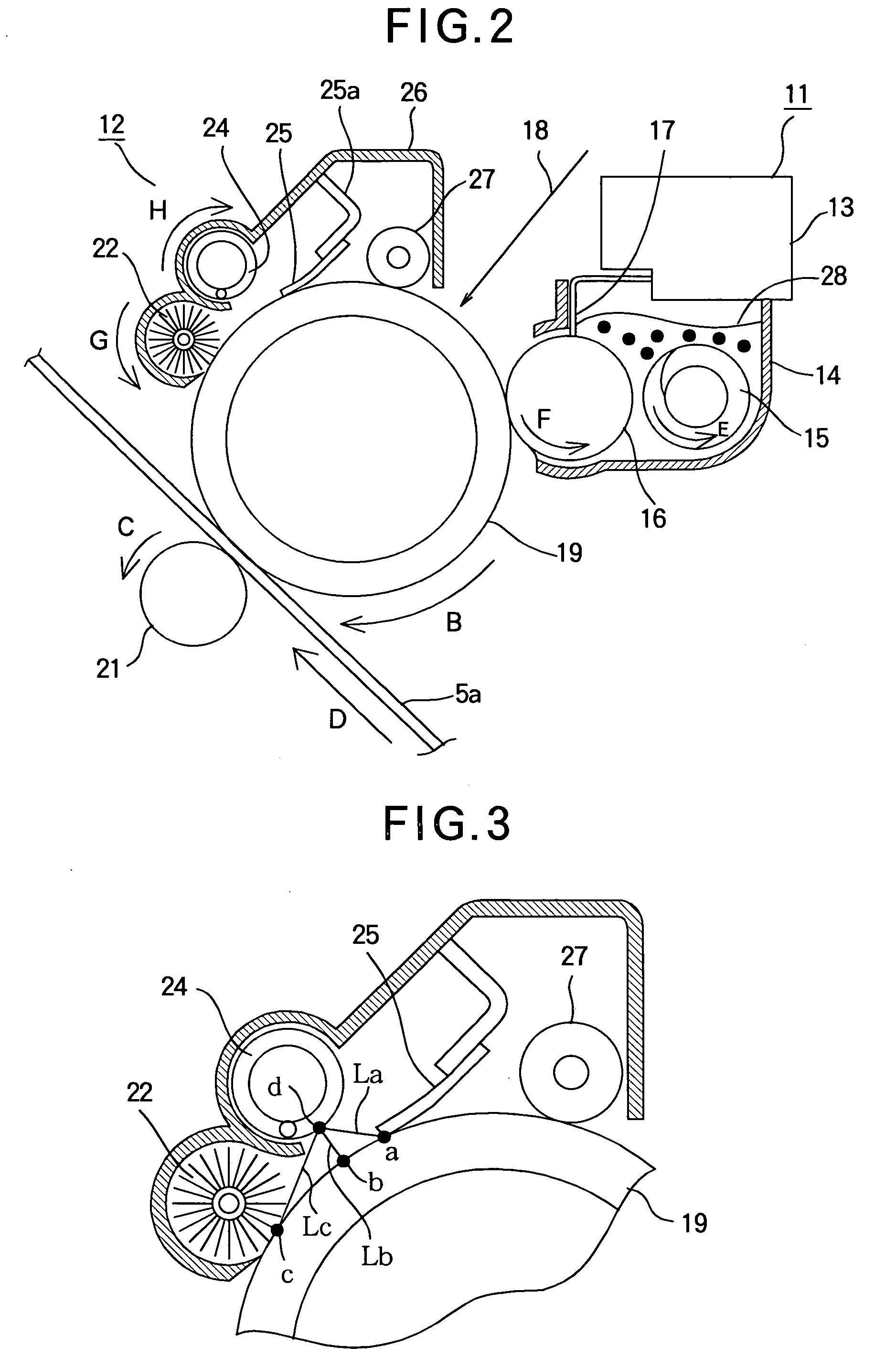
[0049]FIG. 8 is a side view illustrating the cleaning unit and the developing unit according to a second embodiment. The toner transporting member 24 and a mounting portion 26c that accommodates a solid lubricant 31 are disposed to surround the cleaning brush 22. The mounting portion 26c is downstream of the toner transporting member 24 with respect to a direction shown by arrow G, i.e., the direction of rotation of the cleaning brush 22. The mounting portion 26c accommodates the solid lubricant 31 and a resilient member 30 therein. The resilient member 30 urges the lubricant 31 against the tips of the bristles of the cleaning brush 22. The lubricant 31 is made by first melting a lubrication oil additive that contains zinc stearate as a major component, and then cooling it to a solid state. The rest of the configuration of the second embodiment is the same as that of the first embodiment and the description thereof is omitted.

[0050]FIG. 9 illustrates a pertinent p...

Example

Third Embodiment

[0052]FIG. 10 is a side view illustrating a cleaning unit and a developing unit according to a third embodiment. Referring to FIG. 10, a flicker 26b is located downstream with respect to the rotation of the cleaning brush 22 at a point at which a cleaning brush 22 engages a photoconductive body 19. The flicker 26b is provided on a part of a cover 26, and extends in its longitudinal direction, which is parallel to the rotational axis of the cleaning brush 22. The length of the flicker 26b is the same as or longer than the cleaning brush 22. The flicker 26b is positioned so that when the cleaning brush 22 rotates, the flicker 26b can engage the tip portions of the bristles of the cleaning brush 22 or enter into the bristles. When the cleaning brush 22 rotates, the flicker 26b interferes with the tip partitions of the bristles, causing the bristles to first flex resiliently and then releasing the bristles so that the bristles vibrate to shake the toner particles off th...


PUM


Abstract

A cleaning apparatus is used for cleaning the surface of a photoconductive body. Residual toner on a rotating photoconductive body is collected after transferring a toner image from the photoconductive body onto a print medium, the apparatus includes a first cleaning member, a second cleaning member, and a toner transporting member. The first cleaning member engages the photoconductive body to brush away the residual toner. The second cleaning member is disposed downstream of the first cleaning member with respect to rotation of the photoconductive body. The second cleaning member scrapes the residual toner off the photoconductive body. The toner transporting member is disposed between the first cleaning member and the second cleaning member along a circumferential surface of the photoconductive body. The toner transporting member is positioned with a gap between the photoconductive body and the toner transporting member and transporting the residual toner removed from the photoconductive body.

Description

BACKGROUND OF THE INVENTION [0001] 1. Field of the Invention [0002] The present invention relates to an image forming apparatus such as an electrophotographic recording apparatus, and more particularly to a cleaning apparatus that removes residual toner remaining on a photoconductive body after transfer of a toner image. [0003] 2. Description of the Related Art [0004] A conventional electrophotographic recording apparatus uses an electrophotographic image forming process. A charging unit charges the surface of a rotating photoconductive body uniformly. Then, an exposing unit illuminates the charged surface of the photoconductive body in accordance with print data to form an electrostatic latent image. A developing unit supplies toner to the electrostatic latent image to develop the electrostatic latent image into a toner image. A transfer unit transfers the toner image onto a print medium, which in turn is fused into a permanent image in a fixing unit. A cleaning member is provided ...

Claims


Application Information

Patent Timeline
IPC IPC(8): G03G21/00
CPCG03G21/007G03G2221/001G03G21/0076
Inventor KOYAMA, TESTU
Owner OKI DATA CORP
Why Eureka
Try Eureka