Fuel cell and fuel cell stack

a fuel cell and stack technology, applied in the field of fuel cell systems, can solve the problems of high production cost of fuel cells, inability to suitably dispose of fluid units in the pressure casing b>1, complex structure of the fuel cell stack b>2/b>, etc., and achieve the effect of convenient and efficient collection of electrical energy from fuel cells, simple and compact structure, and more freedom in layou

Inactive Publication Date: 2005-06-23
HONDA MOTOR CO LTD
View PDF3 Cites 14 Cited by
  • Summary
  • Abstract
  • Description
  • Claims
  • Application Information

AI Technical Summary

Benefits of technology

[0010] A general object of the present invention is to provide a fuel cell system having a simple and compact structure wh

Problems solved by technology

However, in the structure of Japanese Patent No. 3,251,919, the fluid units cannot be suitably disposed in the pressure casing 1.
Therefore, the struc

Method used


Image

  • Fuel cell and fuel cell stack
  • Fuel cell and fuel cell stack
  • Fuel cell and fuel cell stack

Examples


Embodiment Construction

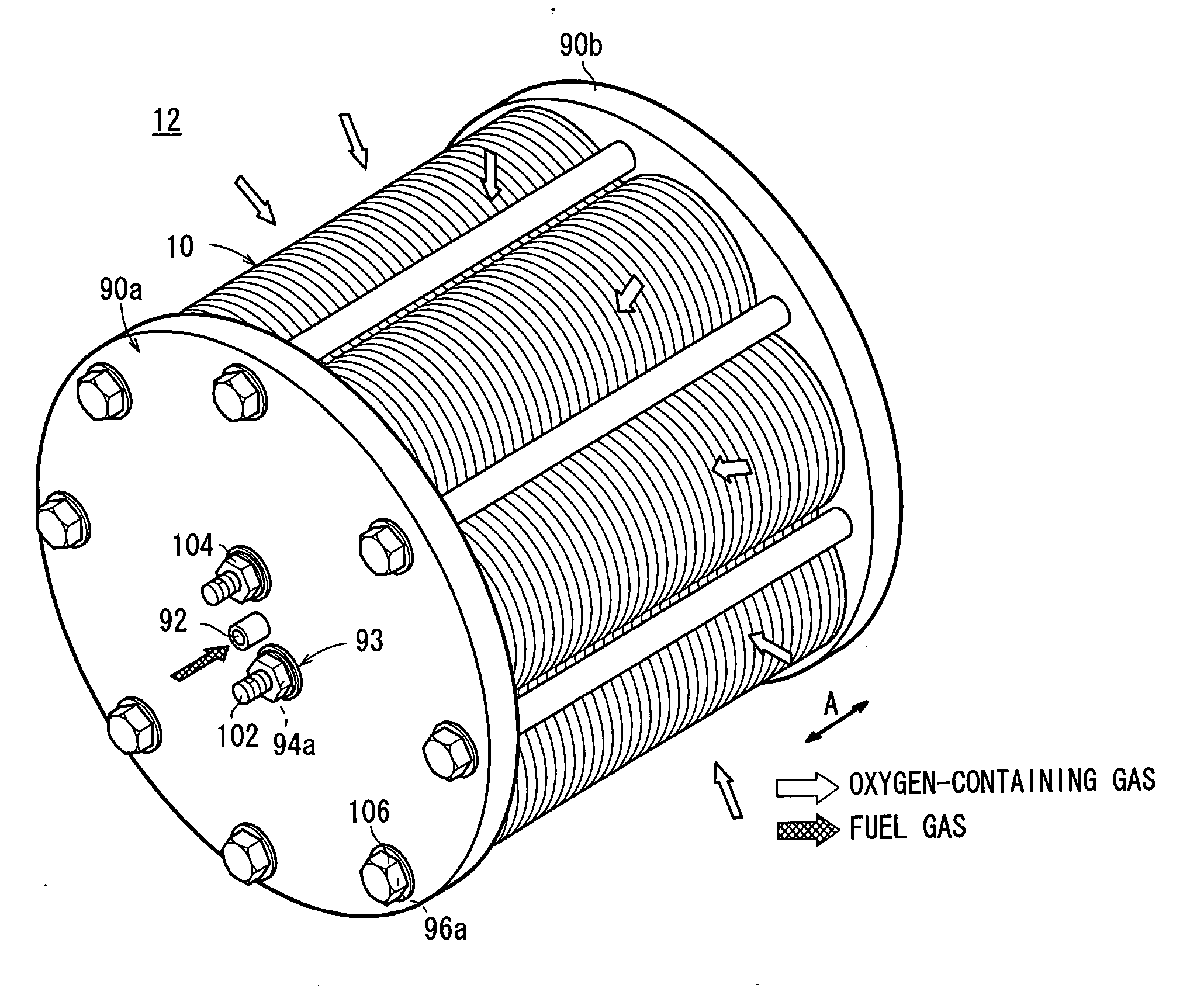
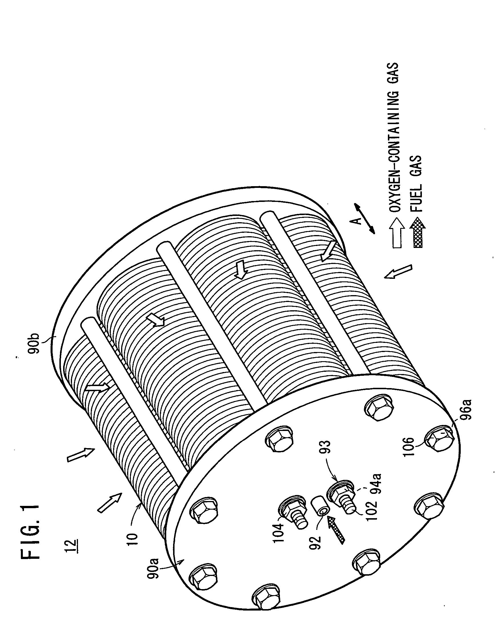
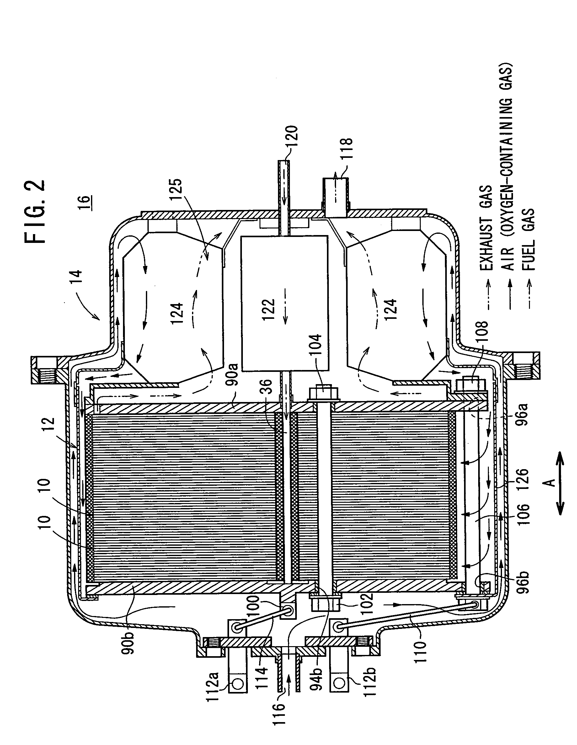
[0027]FIG. 1 is a perspective view schematically showing a fuel cell stack 12 formed by stacking a plurality of fuel cells 10 according to an embodiment of the present invention in a direction indicated by an arrow A. FIG. 2 is a cross sectional view showing part of a fuel cell system 16 in which the fuel cell stack 12 is disposed in a casing 14.

[0028] The fuel cell 10 is a solid oxide fuel cell (SOFC) used in various applications, including stationary and mobile applications. The fuel cell 10 is mounted on a vehicle. As shown in FIGS. 3 and 4, the fuel cell 10 includes an electrolyte electrode assembly 26. The electrolyte electrode assembly 26 includes a cathode 22, an anode 24, and an electrolyte (electrolyte plate) 20 interposed between the cathode 22 and the anode 24. For example, the electrolyte 20 is made of ion-conductive solid oxide such as stabilized zirconia. The electrolyte electrode assembly 26 has a circular disk shape.

[0029] A plurality of, e.g., eight electrolyte el...


PUM


Abstract

A fuel cell system includes a fuel cell stack, a fluid unit including a heat exchanger for heating an oxygen-containing gas, before the oxygen-containing gas is supplied to the fuel cell stack, and a casing for containing the fuel cell stack and the fluid unit. A first output terminal is electrically connected to one electrode, and provided adjacent to an end plate. A second output terminal is electrically connected to another electrode through a tightening member, and provided adjacent to the end plate. The fluid unit is provided adjacent to an end plate.

Description

BACKGROUND OF THE INVENTION [0001] 1. Field of the Invention [0002] The present invention relates to a fuel cell system including a fuel cell formed by sandwiching an electrolyte electrode assembly between a pair of separators. The electrolyte electrode assembly includes an anode, a cathode, and an electrolyte interposed between the anode and the cathode. [0003] 2. Description of the Related Art [0004] Typically, a solid oxide fuel cell (SOFC) employs an electrolyte of ion-conductive solid oxide such as stabilized zirconia. The electrolyte is interposed between an anode and a cathode to form an electrolyte electrode assembly (unit cell). The electrolyte electrode assembly is interposed between separators (bipolar plates). In use, a predetermined numbers of the unit cells and the separators are stacked together to form a fuel cell stack. [0005] In the fuel cell, an oxygen-containing gas or air is supplied to the cathode. The oxygen in the oxygen-containing gas is ionized at the inter...

Claims


Application Information

Patent Timeline
IPC IPC(8): H01M8/02H01M8/04H01M8/06H01M8/12H01M8/24
CPCH01M8/0202H01M8/04014H01M8/04074Y02E60/50H01M8/2475H01M8/248H01M8/0606
Inventor TSUNODA, TADASHI
Owner HONDA MOTOR CO LTD
Why Eureka
Try Eureka