Method for determining the scale of an observation area

a technology of scale and observation area, applied in the direction of material analysis, optically investigating flaws/contamination, instruments, etc., can solve the problems of difficult to determine the imaging or monitoring area of the web , complicated, and in practice, and achieve the effect of fast and easy to recognize the caus

Inactive Publication Date: 2005-09-15
METSO AUTOMATION OY
View PDF6 Cites 12 Cited by
  • Summary
  • Abstract
  • Description
  • Claims
  • Application Information

AI Technical Summary

Benefits of technology

[0028] A significant advantage of the invention is that it makes it possible, in WRM systems or the like, to temporally synchronize the camera units 1 to N, successive in the machine direction, more accurately and more easily than before. By means of the invention, it is now possible to automatically recognize, in recordings from different camera positions brought to comply with each other, a defect or another phenomenon occurring at a given point in the transverse direction of the web, and this information can be utilized further to synchronize image information from different camera units in the machine direction.
[0029] The method according to the invention can be applied for monitoring the moving web itself, or for monitoring the condition of means which are involved in the processing of the web and are in contact with it, such as rolls, reels and various textures (wires, felts). The invention makes it possible to place the camera units or the like more freely and to select the imaging direction without complicating the interpretation of the measuring results because of the different imaging perspectives.
[0030] In an advantageous embodiment of the invention, the shrinkage of the fibre web in the transverse direction of the web is also taken into account, as the web travels from the wet end to the drier final section of the paper machine. When determining the transverse scale of the paper web and the coordinates system for the information measured by imaging, possible edge cutting of the web and possible lateral displacement of the web are also taken into account, if necessary.
[0031] By. taking into account the scale error included in the information measured by imaging and caused by the perspective, as well as the drying shrinkage of the fibre web in the transverse direction, edge cuttings and / or wandering of the web in the lateral direction, if necessary, it is possible to bring the information collected from different imaging or measuring positions into a format which is precisely uniform in the transverse scale. In difference to prior art, this also allows the automatical computer analysis of the measuring results in a significantly more efficient manner than before. Instead of a subjective analysis by the user, the invention makes it possible to use automatic pattern recognition and corresponding image processing techniques in the search for the cause of a given defect in the fibre web or a web break, in images recorded by successive camera units. This makes it faster and easier to recognize the cause of disturbances in the process and also makes it possible to collect statistical material relating to fault situations in a more reliable way than before.

Problems solved by technology

However, in WRM systems and also other corresponding imaging systems, the determination of defects in the cross machine direction is, in practice, complicated by factors to be described below.
This makes it significantly more difficult, in practice, to determine the imaging or monitoring area of the web 21 or other object accurately in the transverse direction, wherein it is also very difficult to determine the precise location of the phenomena visible in the image, in the transverse direction.
Furthermore, it is obvious that the perspective may, in some situations, make the interpretation of the images more difficult also in the scale in the machine direction.
In practice, however, a significant problem in the implementation of the WIS system and other corresponding systems is that, for example because of the space required by the camera beam 41 in the transverse direction of the web, the apparatus required by the system can only be installed in certain locations along the path of the paper web.
Furthermore, the apparatus for a single imaging position will become relatively expensive, due to the large number of camera units 40.
It is obvious that the use of imaging systems of the WIS system type is primarily limited solely to the monitoring of the fibre web itself, because due to the size and structure of the apparatus, its placement to record images of other objects along the path is very difficult.
Furthermore, the structure of the WIS system with the camera beam extending across the whole paper web would significantly encumber the service and maintenance work of the paper machine.

Method used


Image

  • Method for determining the scale of an observation area
  • Method for determining the scale of an observation area
  • Method for determining the scale of an observation area

Examples


Embodiment Construction

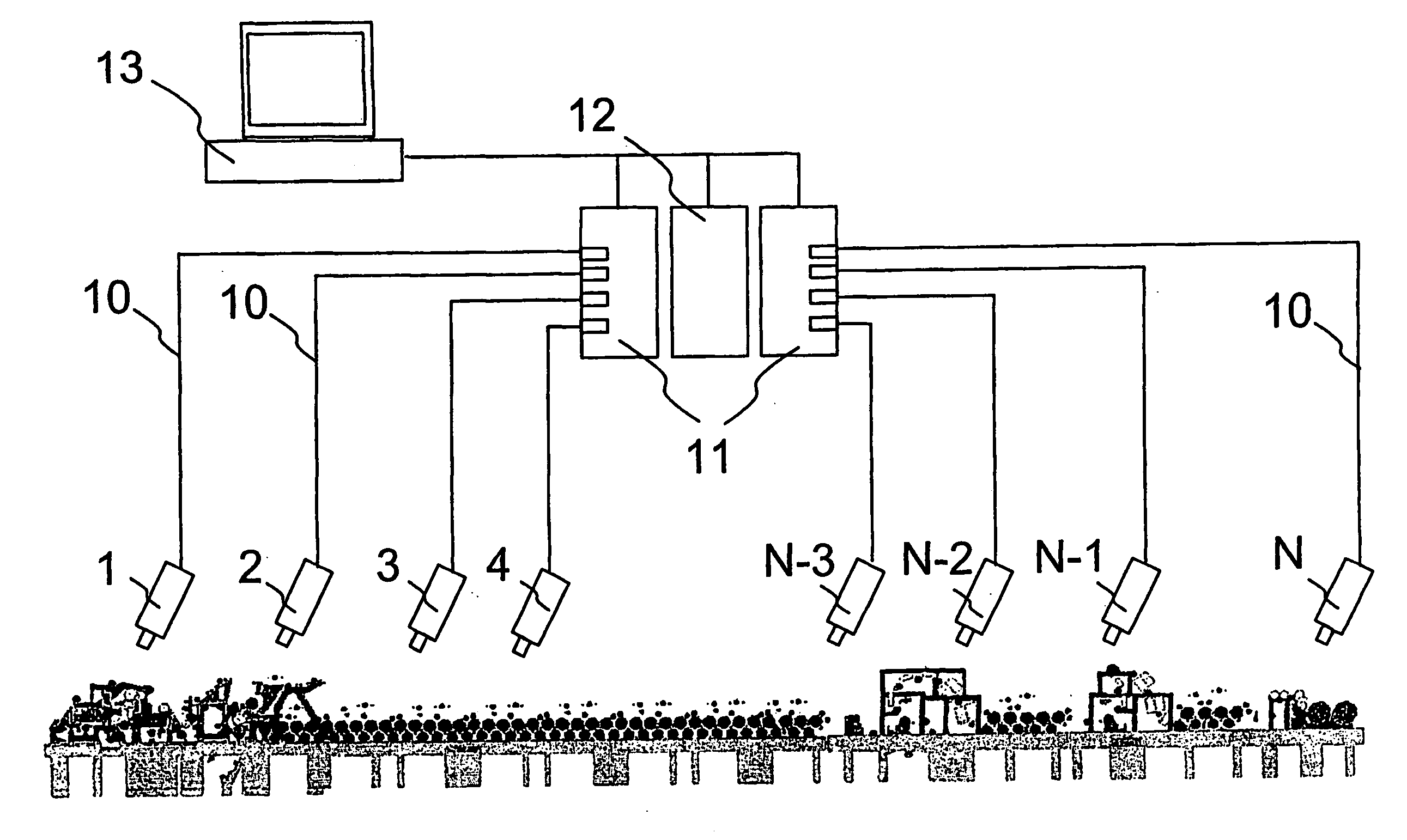
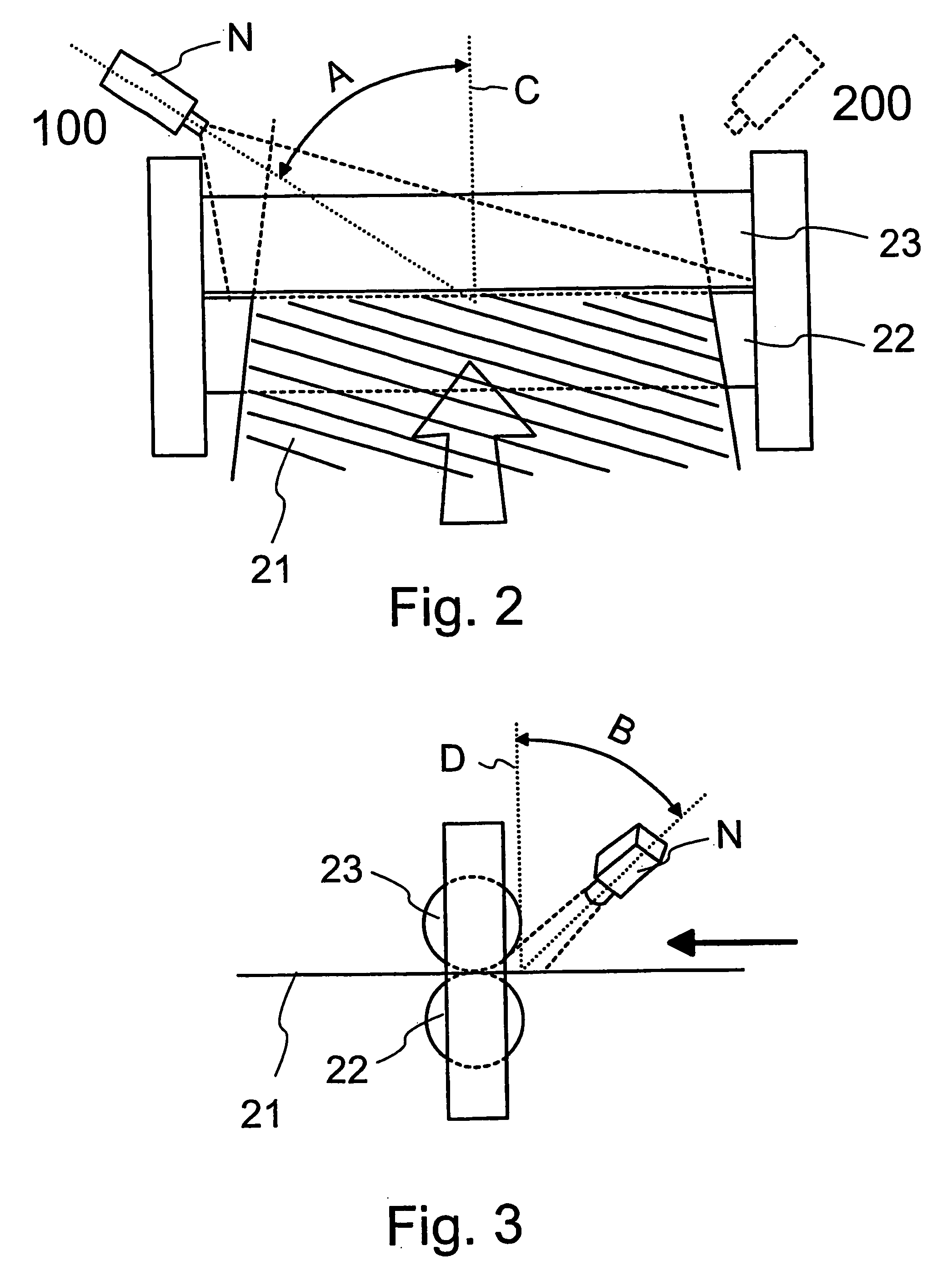
[0042] FIGS. 1 to 4 have been partly discussed already in connection with the description of prior art.

[0043] With reference to FIGS. 5 and 6, we shall still briefly illustrate the effect of perspective caused by the imaging direction on the interpretation of the images.

[0044]FIG. 5 shows a typical image representing a fault situation and recorded by a CCD camera unit at the press of a paper machine. The placement of the camera unit in the imaging position corresponds, in principle, to the situation of FIGS. 2 and 3, in which the camera unit is placed, in relation to the paper web and the paper machine, outside the body of the paper machine, and is trained on the machine. FIG. 5 shows, at the point indicated with an arrow, a beginning web break.

[0045] Because of the directional error caused by the imaging perspective, it is very difficult to evaluate the distances in FIG. 5, particularly in the transverse direction of the paper web. Because of this, it is also impossible to deter...


PUM

PropertyMeasurementUnit
widthaaaaaaaaaa
areaaaaaaaaaaa
imaging measuringaaaaaaaaaa

Abstract

The invention relates to a method in the control of the quality or the condition of a fibre web ( 21 ) on the basis of optical imaging diagnostics, wherein the fibre web ( 21 ) under examination and / or means ( 22, 23 ) relating to the processing of the fibre web are monitored with at least one optical imaging measuring device ( 1 to N). According to the method, the scale of the observation area of said at least one imaging measuring device ( 1 to N) is calibrated, when said measuring device is taken into use, by means of one or more calibration objects placed in the observation area of the measuring device, to correct the perspective error caused by the position between said measuring device and the object ( 21, 22, 23 ) observed by it.

Description

FIELD OF THE INVENTION [0001] The invention relates to a method according to the preamble of the appended claim 1 in the control of the quality or the condition of a fibre web on the basis of optical diagnostics by imaging, the control being applied in connection with the manufacturing or finishing process of a paper web. BACKGROUND OF THE INVENTION AND PRIOR ART [0002] There is a constant aim to increase the web speeds utilized in the manufacturing and finishing processes of paper, paperboard and other corresponding web-like materials in order to improve the production rate. When the web speeds are increased, it is, however, necessary to monitor the function and state of the process in a more detailed manner than before in order to avoid an increase in web breaks that impair the production rate and in various defects in the quality of the fibre web. [0003] One method which has been found to be very efficient in the real-time monitoring of a rapidly moving fibre web and its path is ...

Claims


Application Information

Patent Timeline
Patent Type & Authority Applications(United States)
IPC IPC(8): G01N21/89
CPCG01N21/8903
Inventor AIMONEN, PERTTIKALANIEMI, HANNESMUSTONEN, HARRI
Owner METSO AUTOMATION OY
Why Eureka
Try Eureka