
Valve Positioning Device

a positioning device and valve technology, applied in the field of valve positioning devices, can solve the problems of patient complications, inability to provide a device, and inability to provide an easily identifiable devi

Active Publication Date: 2015-01-15
MEDTRONIC INC
View PDF9 Cites 212 Cited by
  • Summary
  • Abstract
  • Description
  • Claims
  • Application Information

AI Technical Summary

Benefits of technology

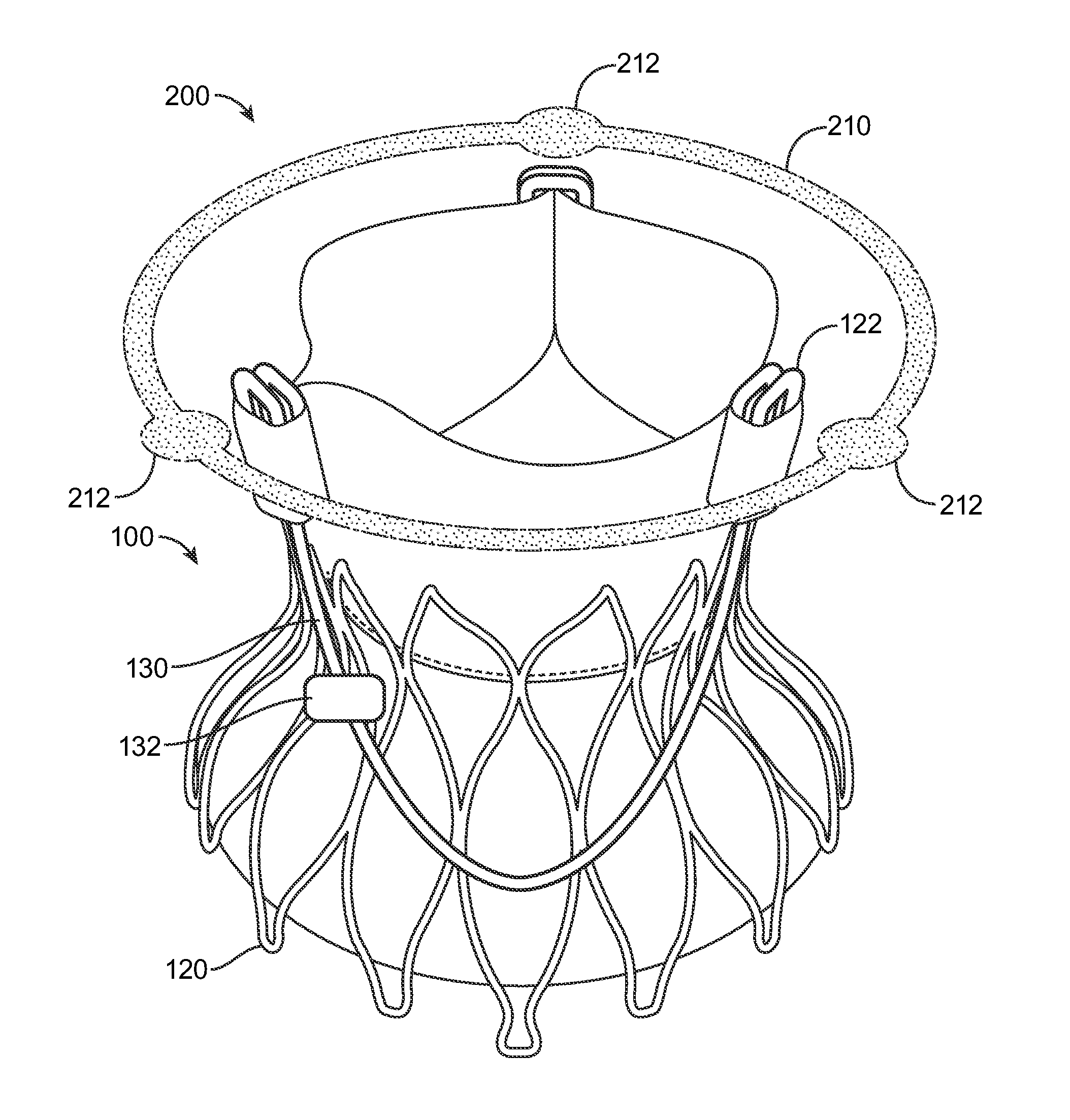
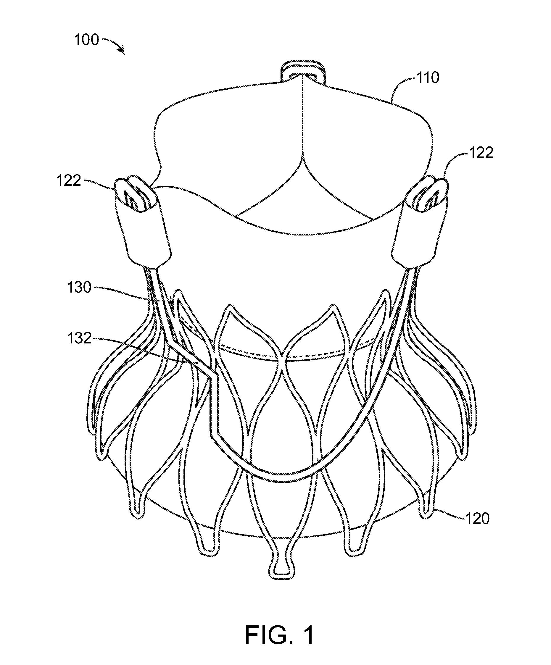
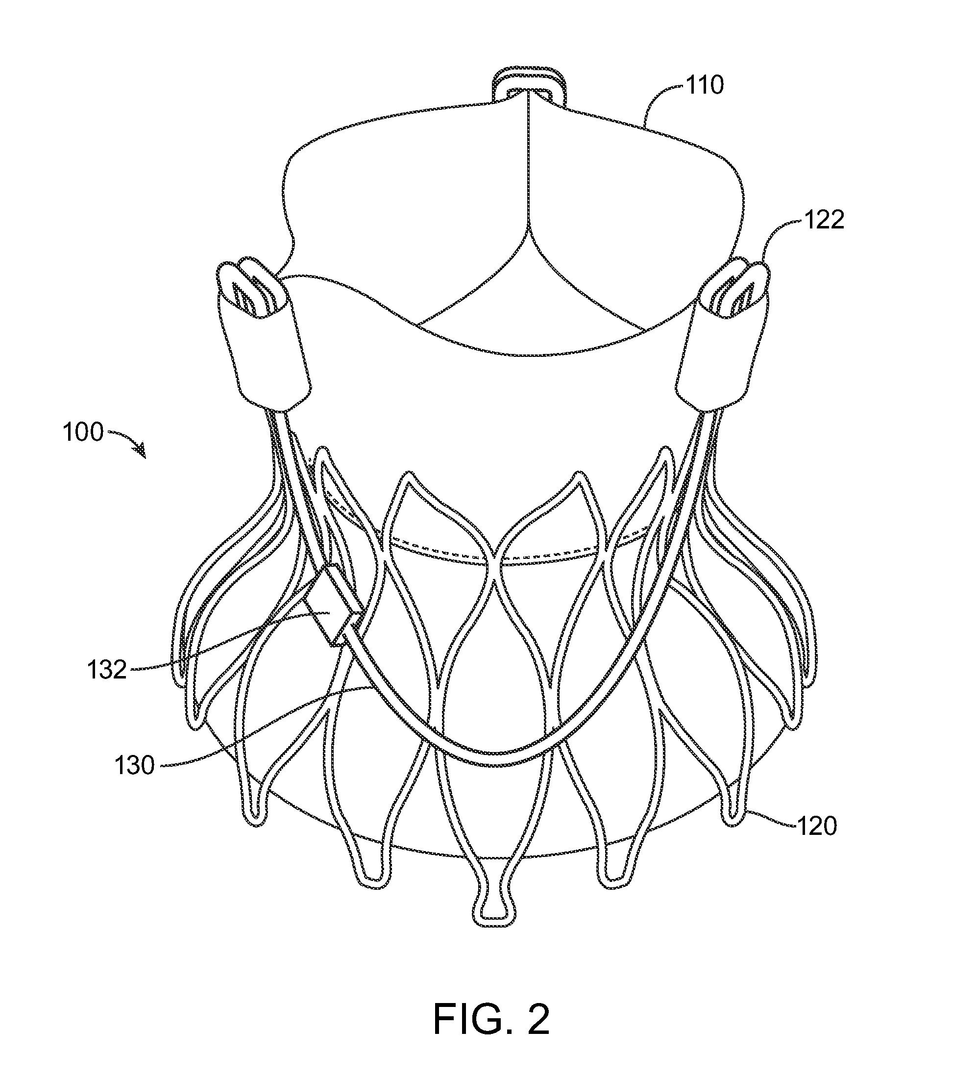
The patent describes a prosthetic heart valve with a valve assembly, frame, and control arm. The control arm has a positional marker, which is a radiographic marker that helps orient the prosthetic heart valve with a native heart valve. The positional marker can be asymmetric and can be positioned closer to one commissural post than the other. The prosthetic heart valve can also have multiple control arms with different shapes and materials. The method of implanting the prosthetic heart valve involves placing it in a heart of a subject and aligning it with the native heart valve. The technical effects of this patent are improved orientation and alignment of the prosthetic heart valve with the native heart valve, which can lead to better outcomes and reduced complications during heart valve replacement surgeries.

Problems solved by technology

More importantly, certain radiographic images do not provide an easily identifiable device to distinguish whether the heart valve prosthesis is correctly positioned and do not provide a device to distinguish how the device is oriented without further investigation.
Incorrect positioning of a heart valve prosthesis can lead to patient complications.

Method used


Image

  • Valve Positioning Device
  • Valve Positioning Device
  • Valve Positioning Device

Examples


Embodiment Construction

[0034]While the disclosure refers to illustrative embodiments for particular embodiments, it should be understood that the disclosure is not limited thereto. Modifications can be made to the embodiments described herein without departing from the spirit and scope of the present disclosure. Those skilled in the art with access to this disclosure will recognize additional modifications, embodiments, and embodiments within the scope of this disclosure and additional fields, in which the disclosed examples could be applied. Therefore, the following detailed description is not meant to be limiting. Further, it is understood that the apparatus and methods described below can be implemented in many different embodiments of hardware. Any actual hardware described is not meant to be limiting. The operation and behavior of the apparatus and methods presented are described with the understanding that modifications and variations of the embodiments are possible.

[0035]References to “one embodime...


PUM


Abstract

Medical devices for positioning a valve in a subject's body, such as a prosthetic heart valve in a subject's heart, are disclosed. The prosthetic heart valve may include a valve assembly, a frame, and a control arm. The prosthetic heart valve may include a commissural post or multiple commissural posts. The prosthetic heart valve may include a positional marker on a control arm. The prosthetic heart valve may include multiple positional markers on one or more control arms. The positional markers can be shapes, characters, or other symbols. The positional markers may themselves be asymmetric. The positional markers may be placed in an asymmetric location on a control arm. The control arm may be asymmetrically shaped.

Description

BACKGROUND[0001]In many medical procedures, a device is inserted temporarily or permanently into a patient. One example includes prosthetic heart valves. Heart valves have been developed that can be inserted via a minimally invasive procedure. Often procedures are performed via a catheter-based delivery system, with the heart valve collapsed on the catheter inserted into the patient, and the heart valve is then expanded when correctly positioned in the patient. The heart valve must be properly positioned before final deployment in the patient.[0002]Existing catheter-based methods prevent certain visualization techniques from being used. Correct positioning of a heart valve prosthesis relative to a native heart valve can be achieved by using radiographic images, including fluoroscopy in some cases. Certain radiographic images are two dimensional and do not indicate depth. More importantly, certain radiographic images do not provide an easily identifiable device to distinguish whether...

Claims


Application Information

Patent Timeline
Patent Type & Authority Applications(United States)
IPC IPC(8): A61F2/24A61B19/00
CPCA61F2/2427A61B19/54A61F2/2418A61F2230/0013A61F2250/0098A61B90/39A61F2250/0014
Inventor O'CONNELL, BARRYCOSTELLO, DECLAN P.COLSON, MICHAEL A.
Owner MEDTRONIC INC
Learn More