
PD in poe system having redundant PSE channel inputs

a technology of pse channel input and poe system, applied in the field of power over ethernet (poe) techniques, can solve the problems of increasing cost, size, power consumption, and hot standby loss, and achieve the effect of saving power and additionally saving power

Active Publication Date: 2015-01-15
ANALOG DEVICES INT UNLTD
View PDF11 Cites 20 Cited by
  • Summary
  • Abstract
  • Description
  • Claims
  • Application Information

AI Technical Summary

Benefits of technology

The patent describes a circuit that allows for the smooth supply of power to a device by ensuring that another device is always available to supply power in case of failure. This is achieved by using auxiliary switches that detect the minimum current required for the device to operate and prevent the device from shutting down even if it is not the active device. This circuit design prevents interruptions in the supply of power and ensures a continuous power supply to the device, even in failure situations.

Problems solved by technology

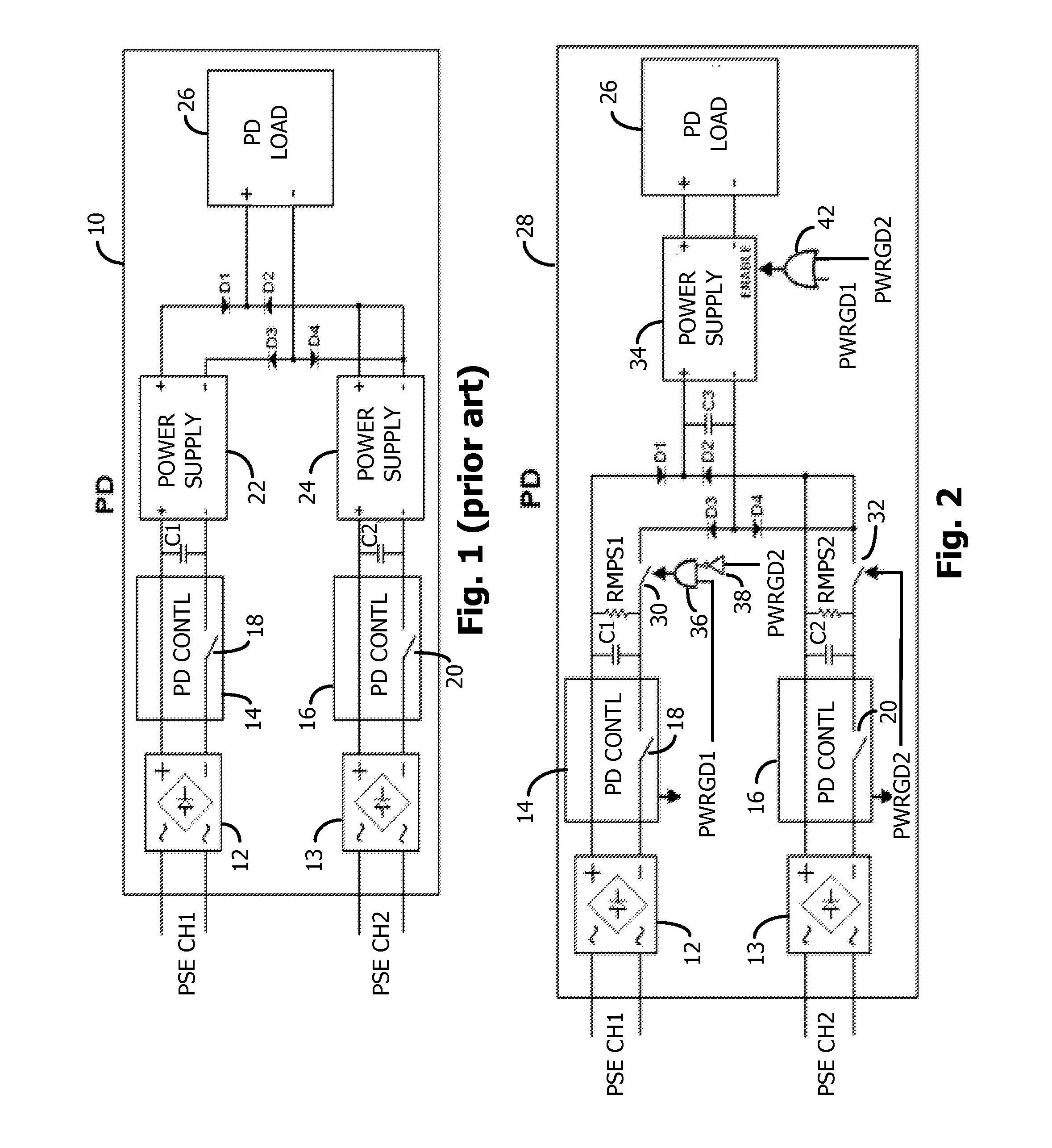
The downside of the design of FIG. 1 is that two power supplies are needed, which adds cost, size, and power consumption.
In that case, hot standby is lost.
However, an operating switching regulator may draw at least 10 mA even when the load is uncoupled from its output.
Disadvantages of this approach include: 1) the PSE for the unused channel will shut down since the minimum current requirement is not met; 2) the unused channel will continually cycle through the PoE detection / classification sequence; and 3) the system is not a hot-standby system since it takes time to power up the unused channel after a failure of the other channel.

Method used


Image

  • PD in poe system having redundant PSE channel inputs
  • PD in poe system having redundant PSE channel inputs
  • PD in poe system having redundant PSE channel inputs

Examples


Embodiment Construction

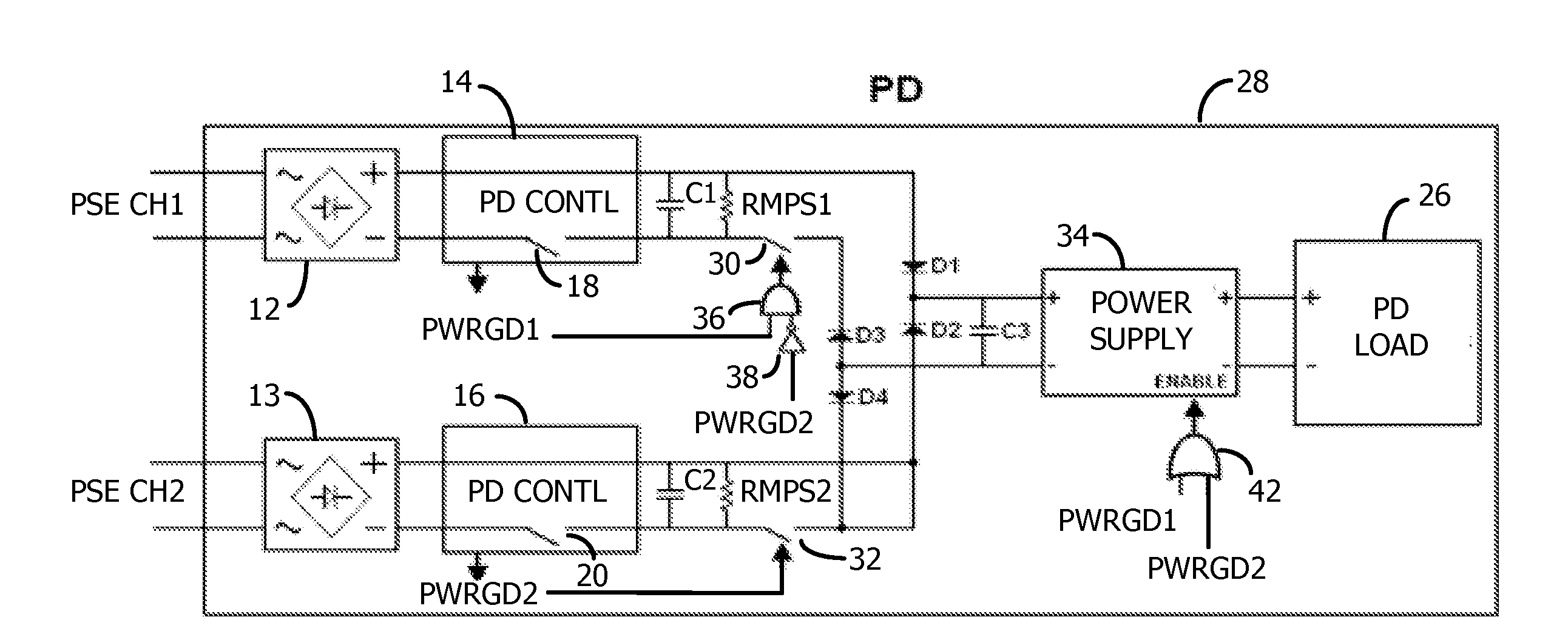
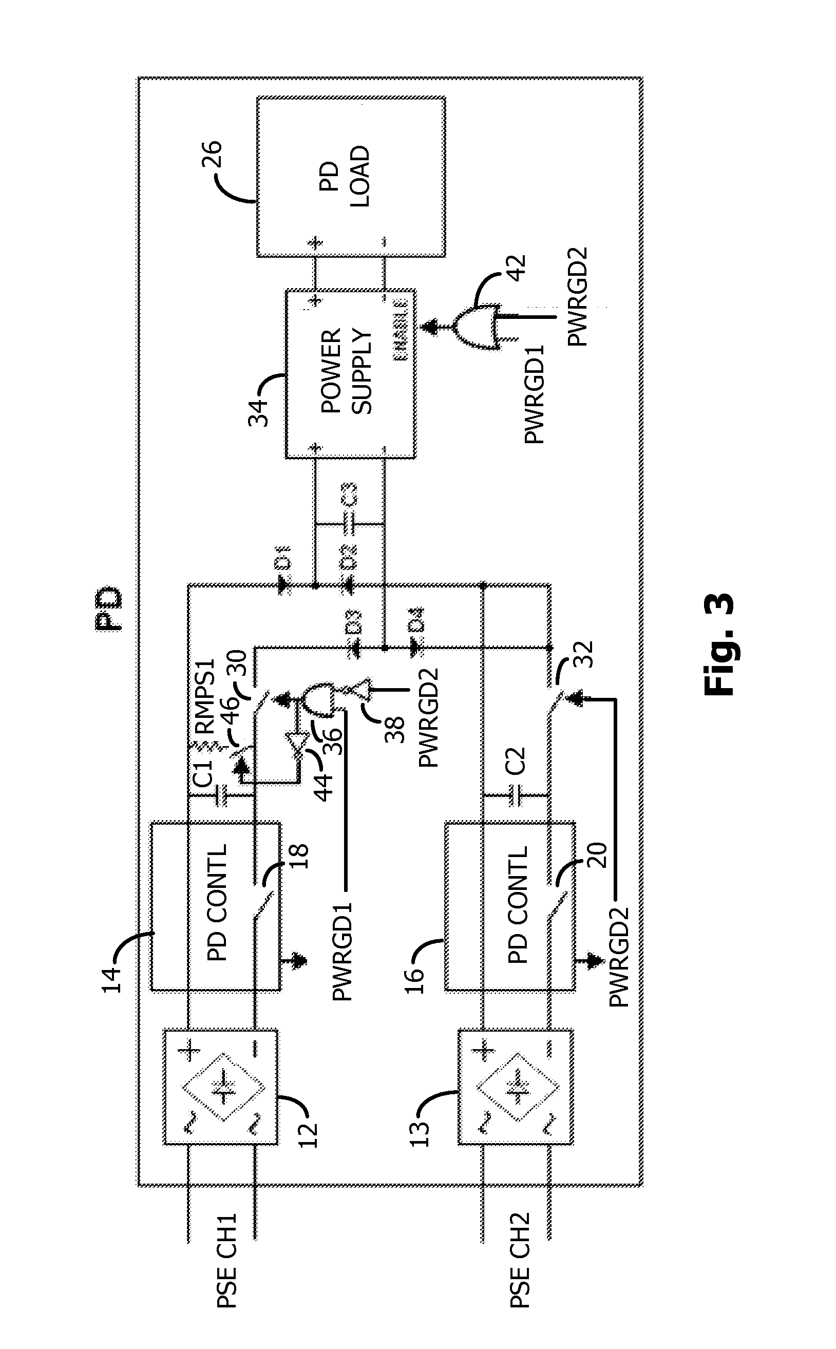
[0027]FIG. 2 illustrates a PD circuit 28 that is a modification of the hot-standby PD circuit of FIG. 1, where there is no interruption in power to the PD load 26 if the primary PSE channel incurs a fault and the PD load 26 is then connected to be powered by the other channel.

[0028]The diode bridges 12 / 13, the PD controllers 14 / 16, and the main PWRGD switches 18 / 20 may be the same as in FIG. 1.

[0029]Upon the system powering up, the PSE controllers (not shown) and the PD controllers 16 / 18 perform a low voltage / current hand-shaking routine in accordance with the IEEE 802.3 standards for PoE. The PD controllers 16 / 18 may be any one of a variety of well-known commercially available PD controllers, such as the LTC4265, available from Linear Technology Corporation. This routine tests for a 25k ohm resistance (a signature impedance) across the two wires for each channel to indicate that the PD is PoE enabled. The 25k ohm resistor may be internal to the PD controller ICs or may be external ...


PUM


Abstract

A Powered Device (PD) in a PoE system has two input channels, each being coupled to a separate Power Sourcing Equipment (PSE) for increased reliability. A first PD controller is coupled to the first channel to perform hand-shaking and closes a first Power Good (PWRGD) switch when the PoE voltage is detected on the first channel. A second PD controller is coupled to the second channel to perform hand-shaking and closes a second PWRGD switch when the PoE voltage is detected on the second channel. A diode bridge couples both channels to a single regulating power supply that supplies power to a load. Auxiliary switches are controlled by the PWRGD signals so that only the first channel or the second channel is coupled to the diode bridge in the event that both channels receive the respective PoE voltages. Therefore, hot standby is provided using only one power supply.

Description

CROSS-REFERENCE TO RELATED APPLICATIONS[0001]This application claims priority from U.S. provisional application Ser. No. 61 / 845,453, filed on Jul. 12, 2013, by Ryan Huff et al., assigned to the present assignee and incorporated herein by reference.FIELD OF THE INVENTION[0002]This invention relates to Power Over Ethernet (PoE) techniques and, in particular, to a Powered Device (PD) having redundant Power Sourcing Equipment (PSE) channel inputs for hot-standby capability, while conforming to the IEEE standards for PoE.BACKGROUND[0003]Currently, Power Over Ethernet (PoE) is standardized by IEEE 802.3af and 802.3at. In PoE, Power Sourcing Equipment (PSE) is connected to a Powered Device (PD) via a standard Ethernet cable, and the PD is supplied DC power over the Ethernet data lines in the cable. In this way, the need for providing any external power source for the PD can be eliminated. The IEEE standard provides various hand-shaking requirements, voltage requirements, current requiremen...

Claims


Application Information

Patent Timeline
Patent Type & Authority Applications(United States)
IPC IPC(8): H04L12/10
CPCH04L12/10G06F1/26H04L49/00
Inventor HUFF, RYAN CHARLESHEATH, JEFFREY LYNNHTOO, KAUNG ZINSU, KIRK TZUKAI
Owner ANALOG DEVICES INT UNLTD
Learn More