Eureka AIR delivers breakthrough ideas for toughest innovation challenges, trusted by R&D personnel around the world.

projector

Active Publication Date: 2015-01-22
SEIKO EPSON CORP
View PDF6 Cites 15 Cited by
  • Summary
  • Abstract
  • Description
  • Claims
  • Application Information

AI Technical Summary

Benefits of technology

The invention aims to provide a projector that can easily adjust the direction and inclination of image projection after being set up on a surface. This allows for flexibility and versatility in the placement of the projector, making it more user-friendly and convenient.

Problems solved by technology

As a result, the position and projection direction of the projector can be changed only in a limited sense, and the changes are not readily made.
For example, the apparatus described in JP-A-2002-344846 uses a bolt / nut-based mechanism that allows adjustment of the angle at which the projector is attached, but the range over which the attachment angle is adjusted is small, and the position where the projector is attached cannot be changed.

Method used


Image

  • projector
  • projector
  • projector

Examples


first embodiment

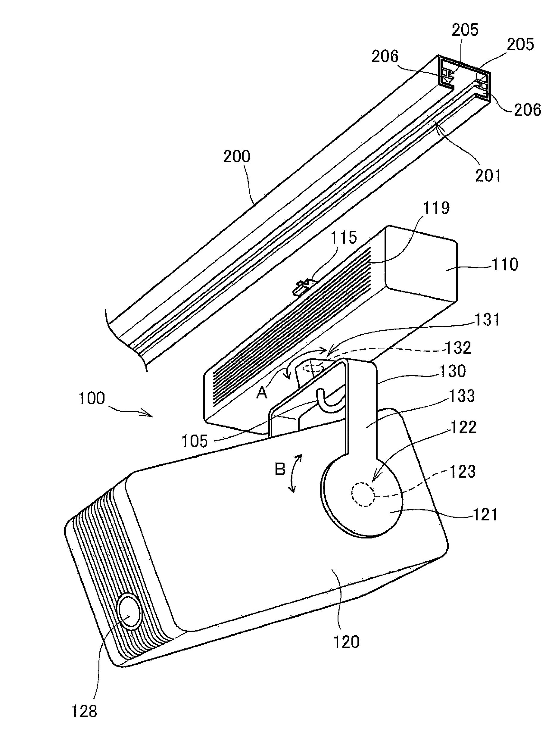
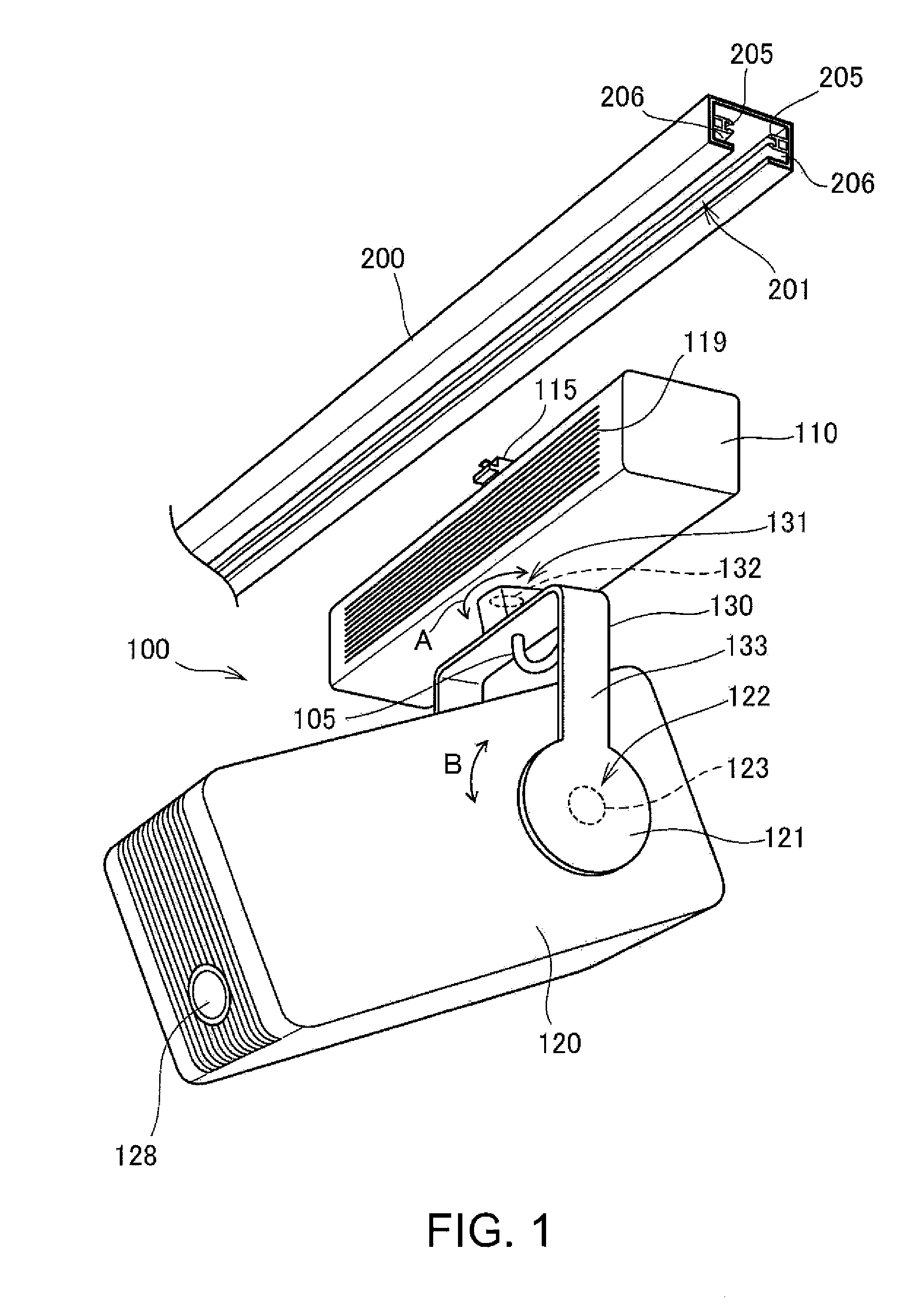
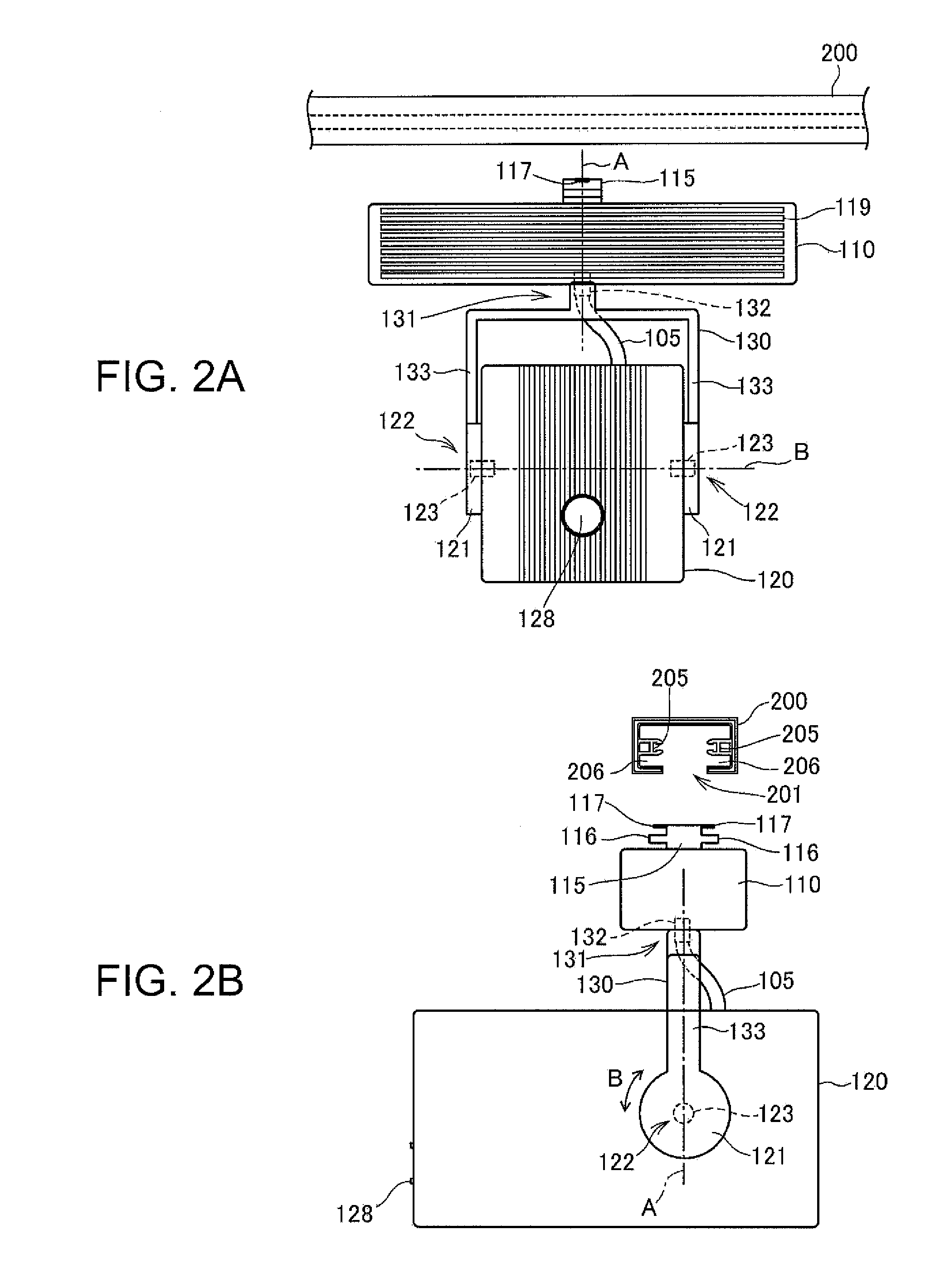
[0041]FIGS. 1, 2A, and 2B show the configuration of a projector 100 according to a first embodiment to which the invention is applied. FIG. 1 is a perspective view. FIG. 2A is a front view, and FIG. 2B is a side view. FIGS. 1, 2A, and 2B also show a duet 200, to which the projector 100 is attached.

[0042]The projector 100 has a light source built therein, modulates light emitted from the light source to form image light, and projects an image on a wall surface or a screen, as will be described later.

[0043]The projector 100 includes a power source accommodation section 110, a projection section body 120, which is separate from the power source accommodation section 110, and a support member 130 (support section), which couples the power source accommodation section 110 and the projection section body 120 to each other. The power source accommodation section 110 has an elongated, substantially box-shaped enclosure, which accommodates a power source circuit 24 (FIG. 4), which will be de...

second embodiment

[0097]FIGS. 5, 6A, and 6B show the configuration of a projector 100 according to a second embodiment to which the invention is applied. FIG. 5 is a perspective view. FIG. 6A is a front view, and FIG. 6B is a side view. FIGS. 5, 6A, and 6B also show a duct 200, to which the projector 100 is attached.

[0098]The projector 100 includes a power source accommodation section 110 (mounter section), a projection section body 120, which is separate from the power source accommodation section 110, and a support member 130 (support section), which couples the power source accommodation section 110 and the projection section body 120 to each other. The power source accommodation section 110 includes a power source accommodation section body 111, which has an elongated, substantially box-like shape, a seating section 112, which is connected to the duct 200, and a support mechanism 140, via which the power source accommodation section body 111 is coupled to the seating section 112.

[0099]The power s...


PUM


Abstract

A projector includes a power source accommodation section and a projection section body. The power source accommodation section is supported by a duct and accommodates a power source circuit that converts electric power supplied from the duct. The projection section body accommodates a projection section that projects an image, and the projection section body is so supported by the power source accommodation section that a direction in which the image is projected is adjustable.

Description

[0001]The entire disclosure of Japanese Patent Application Nos. 2013-150129, filed Jul. 19, 2013 and 2013-150130, filed Jul. 19, 2013 are expressly incorporated by reference herein.BACKGROUND[0002]1. Technical Field[0003]The present invention relates to a projector that projects an image.[0004]2. Related Art[0005]In related art, a projector that projects an image is fixed to a ceiling, a wall surface, or any other surface of a room in some cases, and there is a proposed apparatus for hanging and installing such a projector (see JP-A-2002-344846 and U.S. Pat. No. 8,344,655, for example). In the configuration described in JP-A-2002-344846, a top plate of a projector is securely fixed to a ceiling with bolts. U.S. Pat. No. 8,344,655 describes that a DLP (digital light processor) is supported by a track of a track lighting system to which a plurality of lighting apparatus can be attached and the OLP is controlled via the track.[0006]To fix a projector to a ceiling or any other surface, ...

Claims


Application Information

Patent Timeline
IPC IPC(8): G03B21/16G03B21/14
CPCG03B21/16G03B21/145F16M11/00G03B21/2033G03B21/208G03B33/06H04N9/31F16M11/10F16M11/18F16M11/2014F16M11/2085F16M11/2092H04N9/3144
Inventor KINEBUCHI, TADASHIYAMAGUCHI, KAORU
Owner SEIKO EPSON CORP
Why Eureka
Eureka Blog
Learn More