Light-emitting device

Inactive Publication Date: 2015-01-22
SEMICON ENERGY LAB CO LTD
View PDF15 Cites 83 Cited by
  • Summary
  • Abstract
  • Description
  • Claims
  • Application Information

AI Technical Summary

Benefits of technology

[0019]According to one embodiment of the present invention, a foldable light-emitting device

Problems solved by technology

For example, portable information processors are often used outdoors, and force might be accid

Method used


Image

  • Light-emitting device
  • Light-emitting device
  • Light-emitting device

Examples


embodiment 1

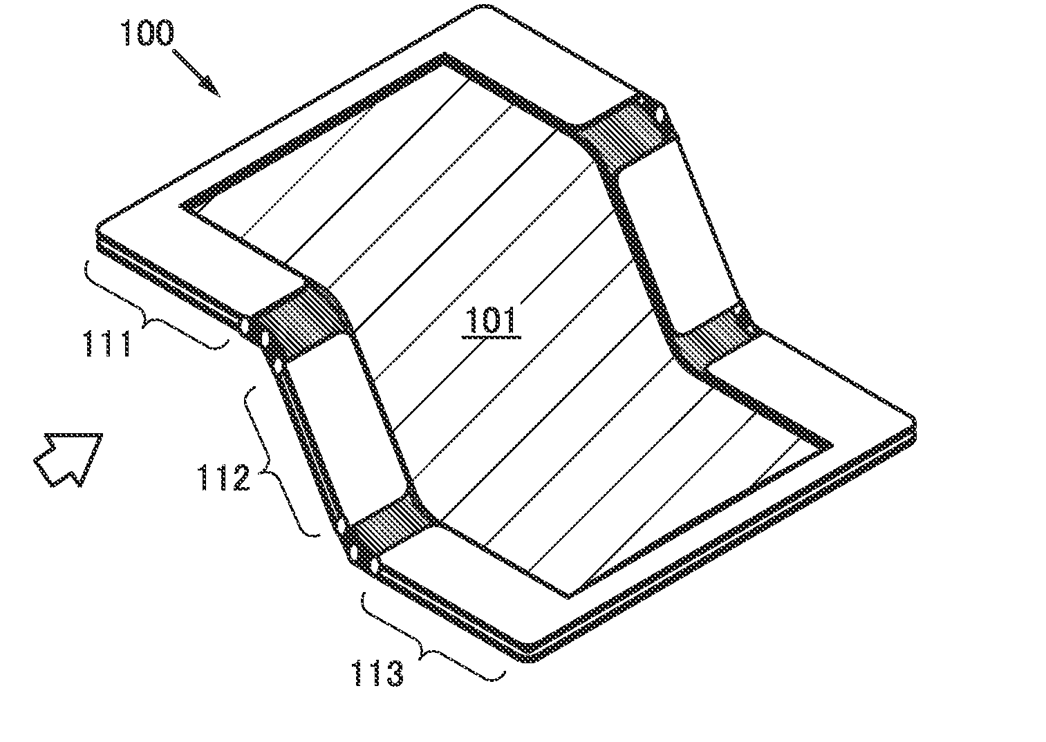
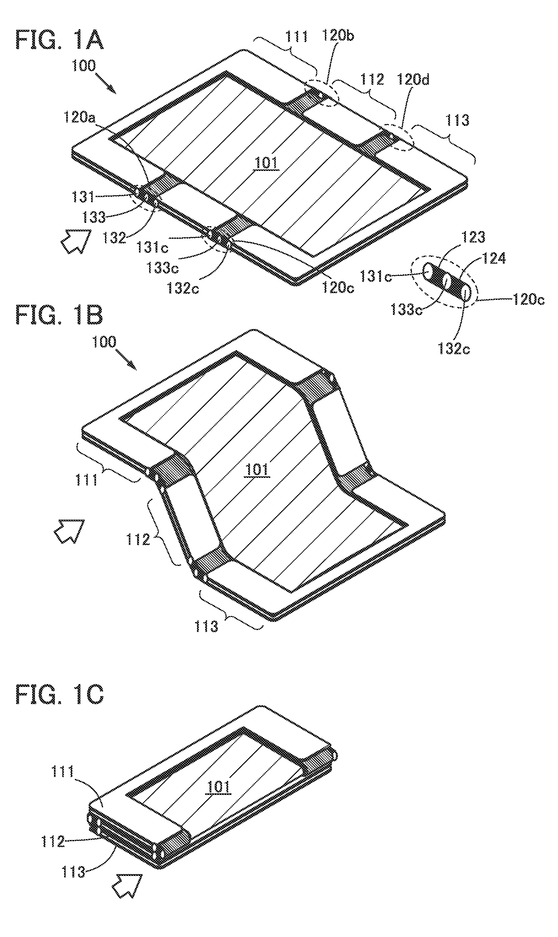
[0032]In this embodiment, the structure of a light-emitting device 100 of one embodiment of the present invention is described with reference to FIGS. 1A to 1C, FIGS. 2A to 2C, FIGS. 3A1 to 3B2, and FIGS. 4A to 4C.

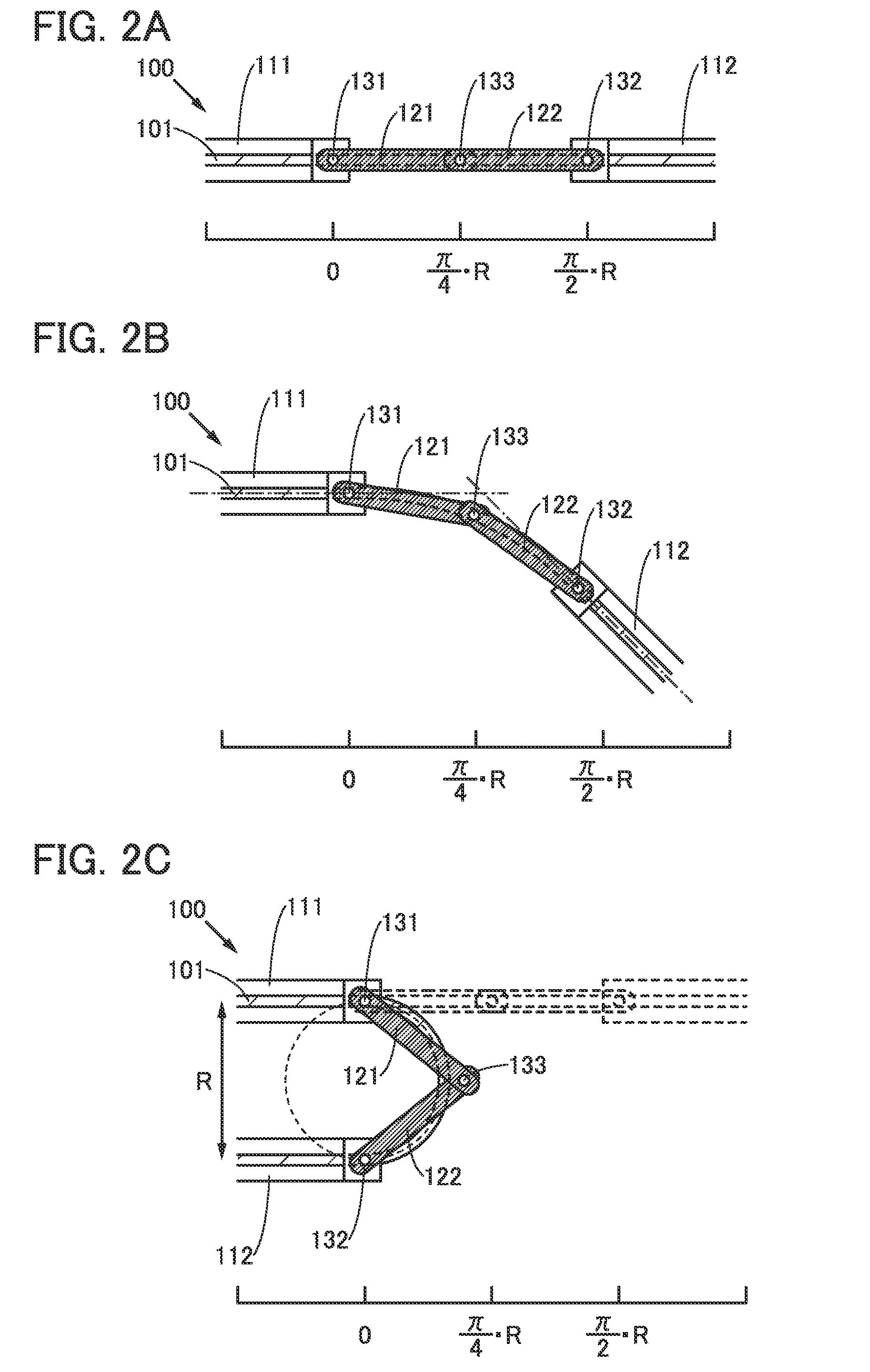
[0033]FIGS. 1A to 1C are perspective views illustrating the structure of a light-emitting device 100 of one embodiment of the present invention. FIG. 1A illustrates the light-emitting device 100 in a developed state, FIG. 1B illustrates the light-emitting device 100 of FIG. 1A in a bent state, and FIG. 1C illustrates the light-emitting device 100 of FIG. 1A in a folded state.

[0034]FIGS. 2A to 2C are side views each illustrating the state of a hinge portion of the light-emitting device 100 of one embodiment of the present invention. FIG. 2A is a side view illustrating the structure of the hinge portion of the light-emitting device 100 in a developed state, FIG. 2B is a side view illustrating the structure of the hinge portion of the light-emitting device 100 in a bent state...

modification example 1

[0056]A modification example of this embodiment is described with reference to FIGS. 3A1 to 3B2.

[0057]FIGS. 3A1 to 3B2 are side views illustrating the structure of a hinge portion of each of the light-emitting device 100B and the light-emitting device 100C of one embodiment of the present invention.

[0058]FIG. 3A is a side view illustrating the structure of a hinge portion of the light-emitting device 100B in a developed state, and FIG. 3A2 is a side view illustrating the structure of the hinge portion of the light-emitting device 100B in a folded state.

[0059]FIG. 3B1 is a side view illustrating the structure of a hinge portion of the light-emitting device 100C in a developed state, and FIG. 3B2 is a side view illustrating the structure of the hinge portion of the light-emitting device 100C in a folded state.

[0060]In the light-emitting device 100B described in the modification example of this embodiment, a distance from the first shaft 131 to the third shaft 133, a distance from the ...

modification example 2

[0069]A modification example of this embodiment is described with reference to FIGS. 4A to 4C.

[0070]FIGS. 4A to 4C are side views illustrating the structure of a hinge portion of a light-emitting device 100D of one embodiment of the present invention.

[0071]FIG. 4A illustrates a hinge portion of the light-emitting device 100D in a developed state, FIG. 4B illustrates the hinge portion of the light-emitting device 100D in a bent state, and FIG. 4C illustrates the hinge portion of the light-emitting device 100D in a folded state.

[0072]The light-emitting device 100D is different from the light-emitting device 100 described using FIGS. 2A to 2C in that the first arm 121 and the second arm 122 are folded between the first support panel 111 and the second support panel 112. The other structures of the light-emitting device 100D are the same as those of the light-emitting device 100.

[0073]This embodiment can be combined with any of the other embodiments in this specification as appropriate....


PUM


Abstract

A foldable light-emitting device is provided. Furthermore, a light-emitting device which can be developed is provided. The light-emitting device includes a light-emitting panel having flexibility, two support panels which support the light-emitting panel, and arms which are connected to the respective panels to be rotatable. Furthermore, the light-emitting device has a structure in which the two support panels, which are apart from each other and connected to the two arms that are connected to be rotatable, support the light-emitting panel. Accordingly, the light-emitting device can be folded so that the two support panels are apart from each other.

Description

TECHNICAL FIELD[0001]The present invention relates to an object, a method, or a manufacturing method. In addition, the present invention relates to a process, a machine, manufacture, or a composition of matter. In particular, the present invention relates to, for example, a semiconductor device, a display device, a light-emitting device, a power storage device, a driving method thereof, or a manufacturing method thereof. In particular, the present invention relates to a light-emitting device.BACKGROUND ART[0002]The social infrastructures relating to means for transmitting information have advanced. This has made it possible to acquire, process, and send out many pieces and various kinds of information with the use of an information processor not only at home or office but also at other visiting places.[0003]With this being the situation, portable information processors are under active development.[0004]For example, portable information processors are often used outdoors, and force ...

Claims


Application Information

Patent Timeline
IPC IPC(8): G06F1/16
CPCG06F1/1652G06F1/1618G06F1/162G06F1/1626G06F1/1637
Inventor TSUKAMOTO, YOSUKE
Owner SEMICON ENERGY LAB CO LTD
Why Eureka
Try Eureka