Wrappable Protective Sleeve With Closure And Locating Feature And Methods Of Construction And Use Thereof

a protective sleeve and closure technology, applied in the field of protective sleeves, can solve the problems of labor expense and time, bulky and relatively heavy, and laborious application, and achieve the effect of reducing labor costs and tim

Active Publication Date: 2015-01-29
FEDERAL MOGUL POWERTAIN LLC
View PDF5 Cites 11 Cited by
  • Summary
  • Abstract
  • Description
  • Claims
  • Application Information

AI Technical Summary

Benefits of technology

[0007]In accordance with another aspect of the invention, the opposite edges of the sleeve wall are spaced from one another along a width of the wall and the release paper has a width less than the width of the wall.

Problems solved by technology

Although tape and tie wraps devices can prove effective, they come at a cost by having to have them in inventory, and in addition, further require labor expense and time for application.
Further, particularly with tape, it can become bulky and relatively heavy, and further yet, subsequent removal, such as may be necessary to service the elongate member, can prove laborious.
Unfortunately, the complex protective sleeves, generally having specialized T-shaped configurations themselves to allow them to be wrapped conformingly about the T-shaped union, are expensive in manufacture, and further, can require a certain degree of expertise and experience to apply.
As for use of tape, the same issues discussed previously, namely, inventory costs and laborious application and removal, hold true to an even increased degree given the complexity of having to wrap the tape about a T-shape configuration.

Method used


Image

  • Wrappable Protective Sleeve With Closure And Locating Feature And Methods Of Construction And Use Thereof
  • Wrappable Protective Sleeve With Closure And Locating Feature And Methods Of Construction And Use Thereof
  • Wrappable Protective Sleeve With Closure And Locating Feature And Methods Of Construction And Use Thereof

Examples


Embodiment Construction

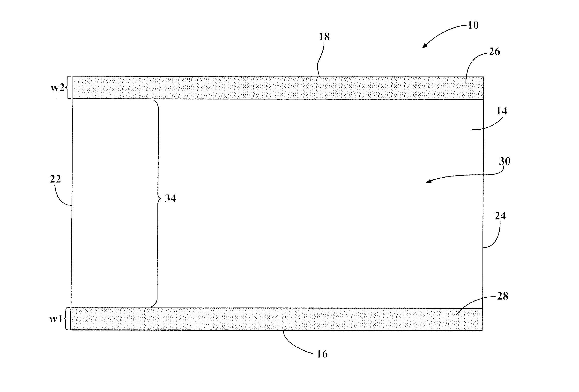
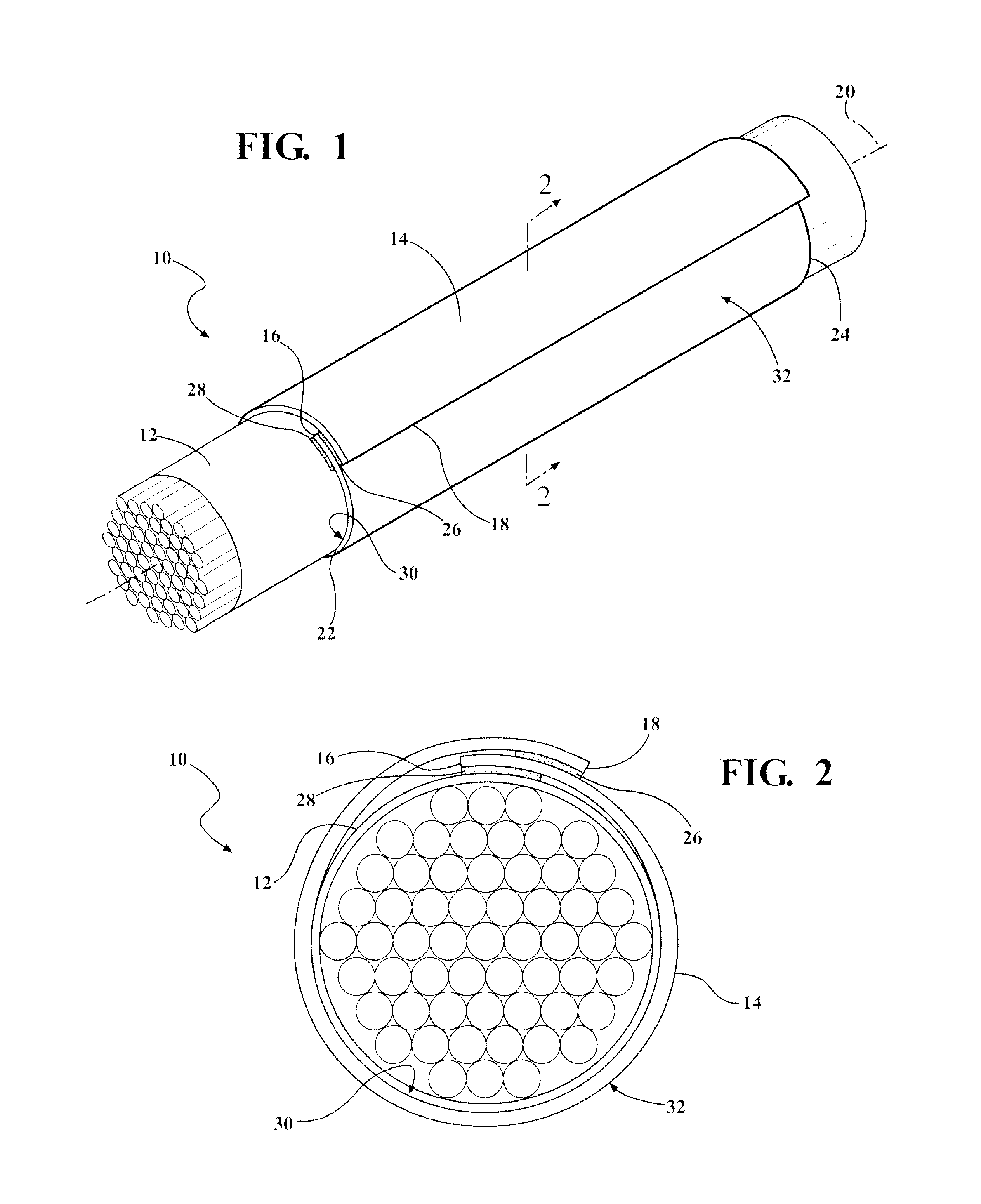
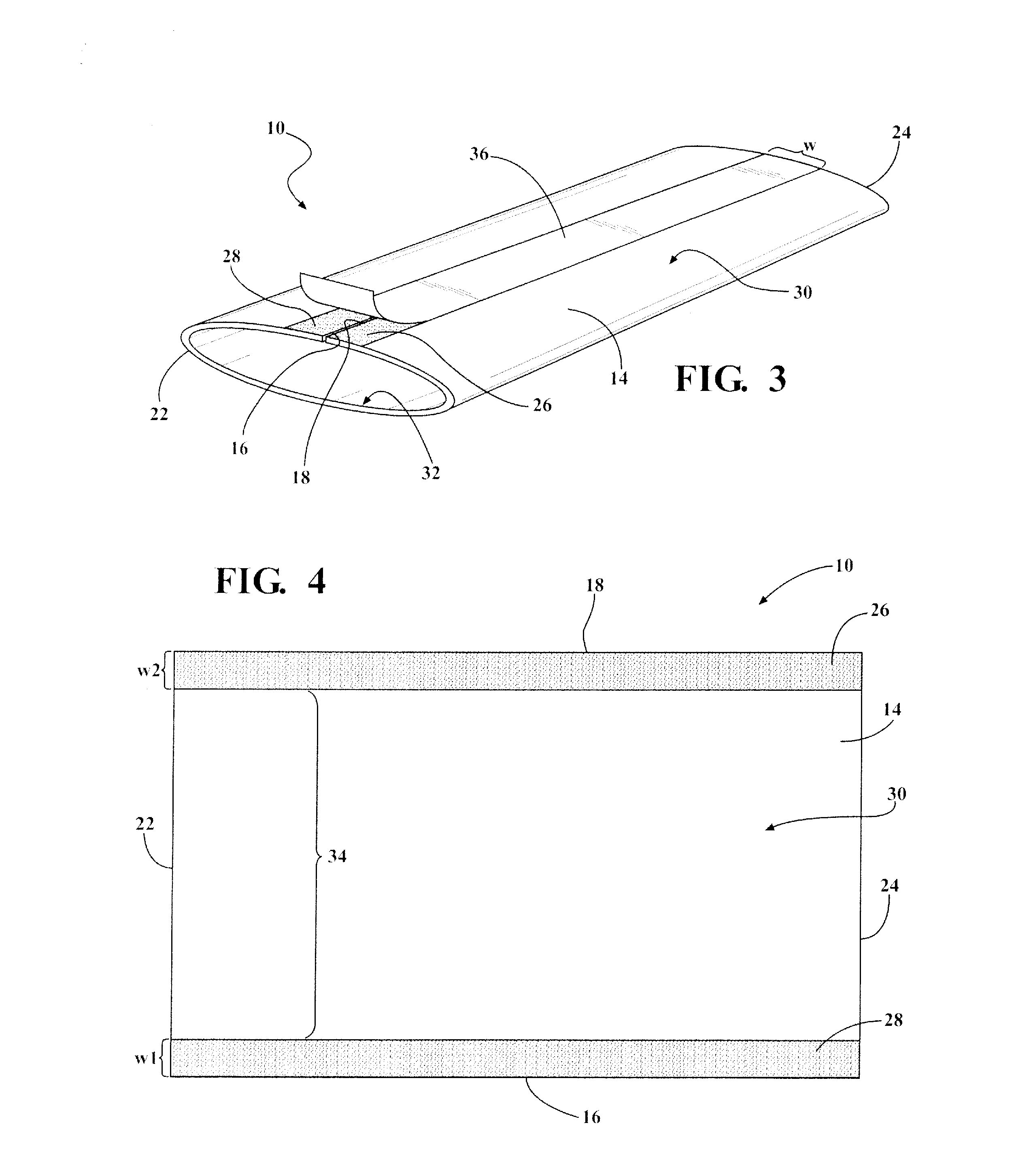
[0033]Referring in more detail to the drawings, FIG. 1 illustrates a wrappable textile sleeve 10 constructed in accordance with one aspect of the invention shown wrapped about an elongate member 12 to be protected, such as a wire harness or pipe, by way of example and without limitation. The textile sleeve 10 has a wall 14 sized to be wrapped circumferentially about the elongate member 12 to be protected such that opposite, lengthwise extending edges 16, 18, which extend generally parallel to one another and generally parallel to a central longitudinal axis 20 of the sleeve 10 between opposite ends 22, 24, are brought into overlapping, fixed relation with one another. In addition to the opposite edges 16, 18 of the wall 14 being fixed in a circumferentially wrapped configuration, thereby providing the desired protection to the elongate member 12 about the entire circumference of the elongate member 12, the wall 14, as discussed further below, is fixed to the elongate member 12 to pr...


PUM

PropertyMeasurementUnit
flexibleaaaaaaaaaa
widthaaaaaaaaaa
adhesiveaaaaaaaaaa

Abstract

A wrappable protective sleeve for providing protection to at least one elongate member contained therein and methods of construction and use thereof are provided. The sleeve includes a flexible textile wall having opposite inner and outer faces bounded by opposite edges and opposite ends. The opposite edges extend generally parallel to one another between the opposite ends. A pair of adhesive layers is bonded to the inner face, with each of the adhesive layers being spaced from one another. The adhesive layers extend between the opposite ends adjacent the opposite edges. Further, a release paper is releasably adhered to the pair of adhesive layers for subsequent removal and use of the sleeve.

Description

BACKGROUND OF THE INVENTION[0001]1. Technical Field[0002]This invention relates generally to protective sleeves for providing protection to elongate members contained therein, and more particularly to wrappable protective sleeves and to their methods of construction and use.[0003]2. Related Art[0004]Wrappable protective sleeves for providing protection to a straight elongate member contained therein are known. Typically, wrappable protective sleeves are fixed about the elongate member by a separate fastening feature, such as with tape or tie wraps wrapped circumferentially about the sleeve wall. Although tape and tie wraps devices can prove effective, they come at a cost by having to have them in inventory, and in addition, further require labor expense and time for application. Further, particularly with tape, it can become bulky and relatively heavy, and further yet, subsequent removal, such as may be necessary to service the elongate member, can prove laborious.[0005]In addition ...

Claims


Application Information

Patent Timeline
Patent Type & Authority Applications(United States)
IPC IPC(8): B32B37/00C09J7/04C09J7/02B32B37/12C09J7/21
CPCB32B37/0076B32B37/1292B32B37/025C09J7/04C09J2400/28B32B2405/00B32B2433/00B32B2571/00C09J7/0228B60R16/0215F16L57/00H02G3/0481C09J7/401C09J7/21Y10T428/1476Y10T156/1093B29C63/06
Inventor MALLOY, CASSIE M.FERRAND, JEANWINTERS, DANNY E.GAO, TIANQI
Owner FEDERAL MOGUL POWERTAIN LLC
Why Eureka
Try Eureka