Superconducting element with elongated opening and method for manufacturing a superconducting element

a superconducting element and opening technology, applied in the field of superconducting elements, can solve the problems of insufficient time stability of superconducting elements composed or formed from hts coated tapes, and achieve the effects of better time stability of superconducting elements, better stability, and better electrical performan

Inactive Publication Date: 2012-08-23
BRUKER HTS
View PDF2 Cites 10 Cited by
  • Summary
  • Abstract
  • Description
  • Claims
  • Application Information

AI Technical Summary

Benefits of technology

[0023]The shunt layer advantageously comprises a basic conductive layer and a second protection layer, whereby the second protection layer is provided between the first protection layer and the basic conductive layer. The second protection layer is preferably metallic. By providing a second protection layer, the superconducting element comprises a protection layer which is deposited in two steps (deposition of the first protection layer and deposition of the second protection layer, together forming the protection layer), whereby the cutting (e.g. laser beam cutting) is performed between the deposition of the first and the second protection layer. By this procedure, the HTS layer (which is deposited below the first protection layer) is already protected against reactive environment by the first protection layer when the cutting is started (which typically comes along with aggressive/reactive environment for the entire partially prepared coated tape). In turn, the “fresh” edges resulting from the cutting process (edge surfaces of the opening) will still be protected by the second protection layer deposited after the cutting and prior to the deposition of the basic conductive layer of the shunt layer. The deposition of the second conductive layer is advantageous if the materials of the substrate tape and the basic conductive layer only poorly adhere to each other (e.g. a Cu basic conductive layer and a stainless steel substrate). For very special combination of materials and deposition method for the shunt layer, the second protection layer may be omitted (i.e. the shunt layer only consists of the basic conducti

Problems solved by technology

However, the time stability of superconducting elements being composed or formed from HTS coated tapes is not sufficient enou

Method used


Image

  • Superconducting element with elongated opening and method for manufacturing a superconducting element
  • Superconducting element with elongated opening and method for manufacturing a superconducting element
  • Superconducting element with elongated opening and method for manufacturing a superconducting element

Examples


Embodiment Construction

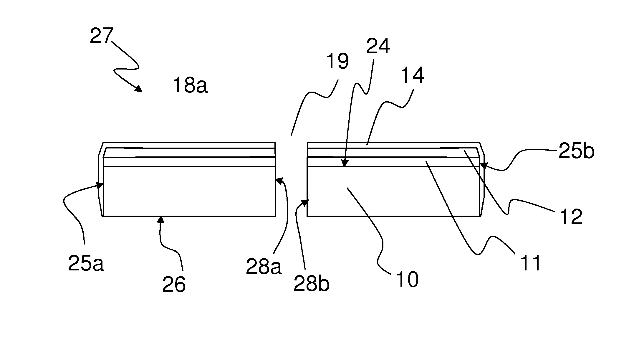
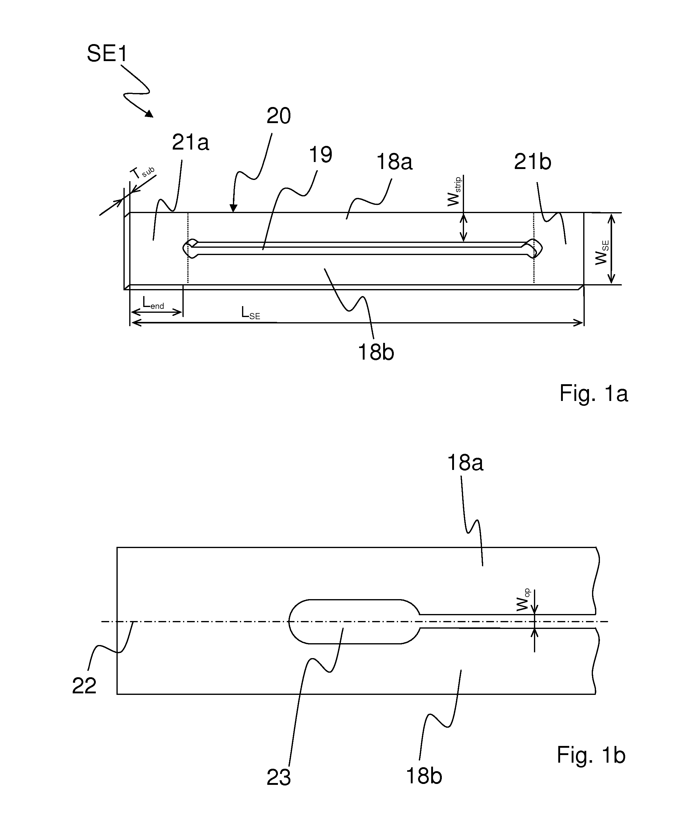
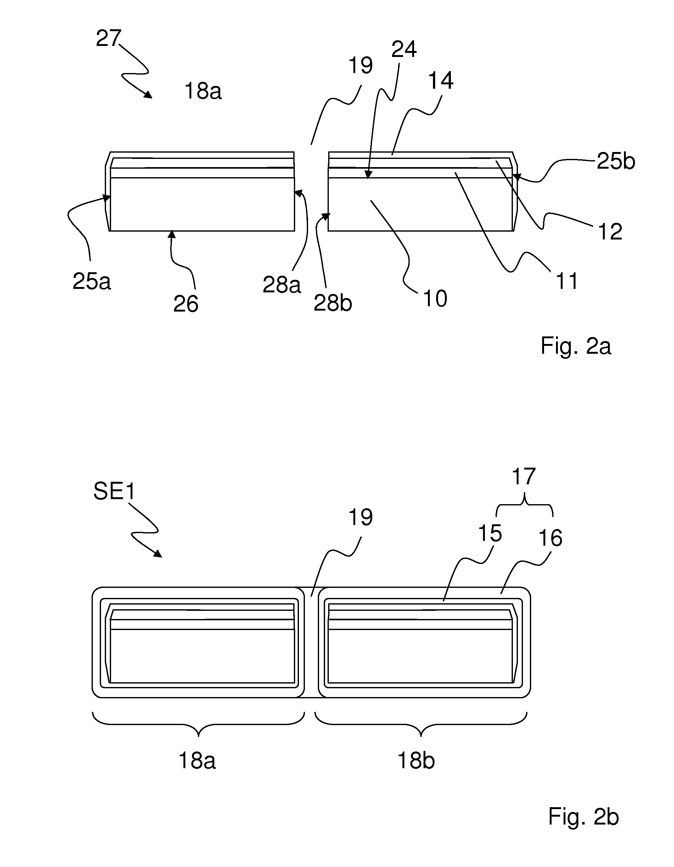
[0058]FIG. 1a shows an inventive superconducting element SE1 with an elongated opening 19 in the form of a slot. The superconducting element SE1 comprises a central section 20, which is adjacent to two end sections 21a, 21b (in FIG. 1a the boundary of the central section 20 to the end sections 21a, 21b is shown by a dashed line). The end sections 21a, 21b may have a length Lend of several widths WSE of the superconducting element SE1. The elongated opening 19 is positioned in the central section 20 of the superconducting element SE1. The ends of the elongated opening 19 are adjacent to the end sections 21a, 21b of the superconducting element SE1. The opening 19 divides the central section 20 into two HTS strips 18a, 18b. The end sections 21a, 21b connect the HTS strips 18a, 18b thereby forming a closed loop that surrounds the opening 19.

[0059]As shown in FIG. 1b the elongated opening 19 is oriented along a longitudinal axis 22 of the superconducting element SE1 and comprises a minim...


PUM


Abstract

A superconducting element (SE1-SE5) with a central section (20) located between two end sections (21a, 21b) of the superconducting element (SE1-SE5), the superconducting element (SE1-SE5) has a substrate tape (10), a buffer layer (11), a high temperature superconducting (HTS) layer (12), a first protection layer (14), and a shunt layer (17), The superconducting element (SE1-SE5) has at least one elongated opening (19) in the central section (20) elongated between the two end sections (21a, 21b), whereby the at least one elongated opening (19) divides the central section (20) of the superconducting element (SE1-SE5) into at least two HTS strips (18a, 18b, 18c), whereby the shunt layer (17) envelops the surface of each of the HTS strips (18a, 18b, 18c). The superconducting element shows improved electrical stabilization and time stability.

Description

[0001]This application claims Paris Convention priority of EP 11 154 949.9 filed Feb. 18, 2011 the complete disclosure of which is hereby incorporated by reference.BACKGROUND OF THE INVENTION[0002]The invention relates to a superconducting element with a central section located between two end sections of the superconducting element, the superconducting element comprising: a substrate tape, a buffer layer, a high temperature superconducting (HTS) layer, a first protection layer, and a shunt layer.[0003]A layered HTS structure, comprising a substrate, a buffer layer, an HTS layer, a capping layer and a stabilizer layer, or a corresponding method for its manufacturing, respectively, is known from U.S. Pat. No. 7,774,035 B2.[0004]The invention deals with high temperature superconducting coated tapes and may be employed, in particular, in the fields of building of magnets, rotating machines, machines and devices for energy storage, energy transmission, and energy distribution.[0005]Supe...

Claims


Application Information

Patent Timeline
IPC IPC(8): H01L39/02H01L39/24B05D5/12B32B3/00
CPCY10T428/24479H01L39/2464H01L39/16H01L39/143H10N60/203H10N60/30H10N60/0661
Inventor USOSKIN, ALEXANDER
Owner BRUKER HTS
Why Eureka
Try Eureka