Automotive tandem alternator having reduced axial length and capable of effectively suppressing magnetic leakage

Inactive Publication Date: 2007-10-18
DENSO CORP
View PDF11 Cites 10 Cited by
  • Summary
  • Abstract
  • Description
  • Claims
  • Application Information

AI Technical Summary

Benefits of technology

[0032]As above, in the tandem alternator according to third aspect, the inside disc portions of the first and second field cores are arranged to be magnetically connected to each other, thereby forming a common magnetic path to the first and second electric power generation units. Further, the widths of the inside disc portions are reduced so that the sum of widths of the inside disc portions is less than tha

Problems solved by technology

Thus, in installation of the tandem alternator 500 to an engine of the vehicle, it is difficult to suitably arrange the alternator 500 without causing interference between the alternator 500 and an intake or exhaust pipe of the engine.
Consequently, it may become difficult to accurately and separately control the power generation units 502 and 50

Method used


Image

  • Automotive tandem alternator having reduced axial length and capable of effectively suppressing magnetic leakage
  • Automotive tandem alternator having reduced axial length and capable of effectively suppressing magnetic leakage
  • Automotive tandem alternator having reduced axial length and capable of effectively suppressing magnetic leakage

Examples


first embodiment

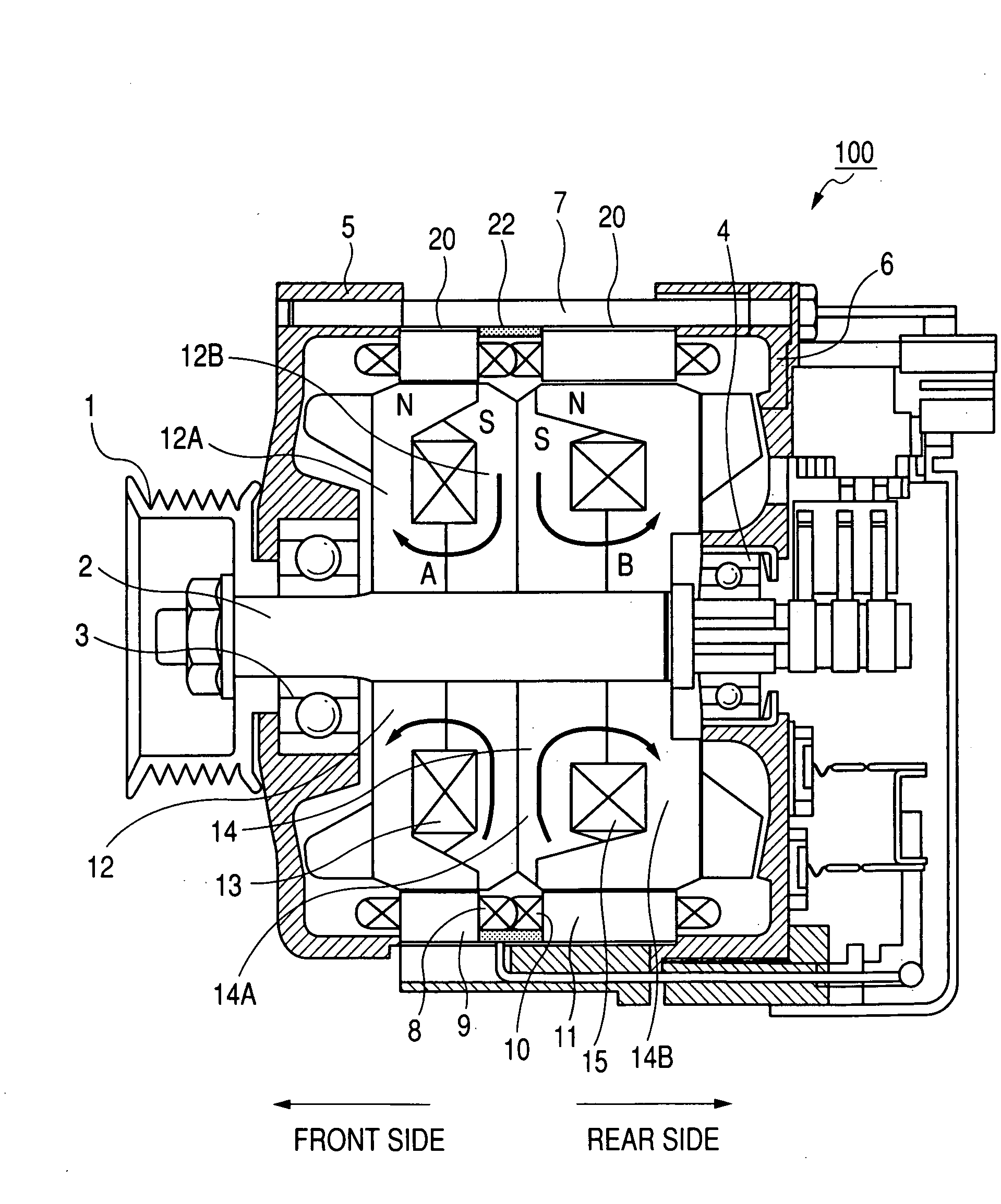
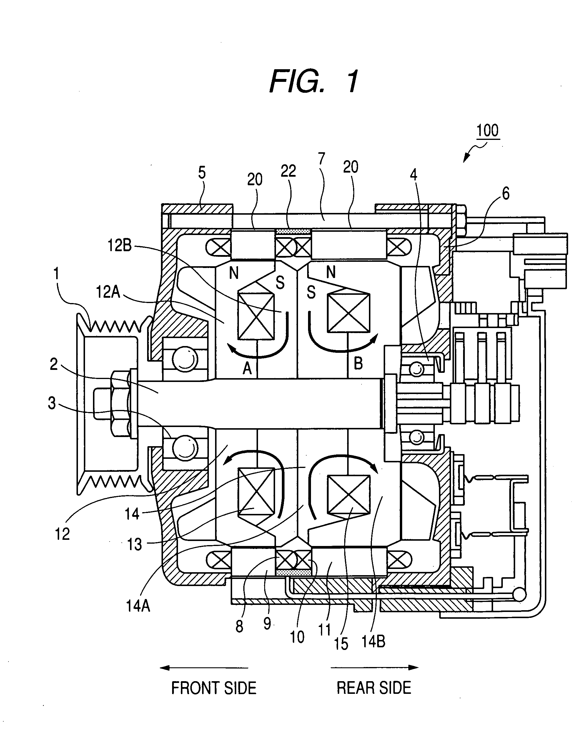
[0043]FIG. 1 shows the overall configuration of a tandem alternator 100 according to the first embodiment of the invention.

[0044]The alternator 100 is designed for use in an automobile. More specifically, the alternator 100 is configured to be driven by an engine (not shown) of the automobile via a pulley 1 that is fitted on a rotary shaft 2 of the alternator 100.

[0045]The rotary shaft 2 is rotatably supported by a front bearing 3 and a rear bearing 4, which are respectively provided in a front housing 5 and a rear housing 6 of the alternator 100. In other words, the front and rear housings 5 and 6 together rotatably support the rotary shaft 2 via the front and rear bearings 3 and 4. In the present embodiment, both the front and rear housings 5 and 6 are made of a nonmagnetic material.

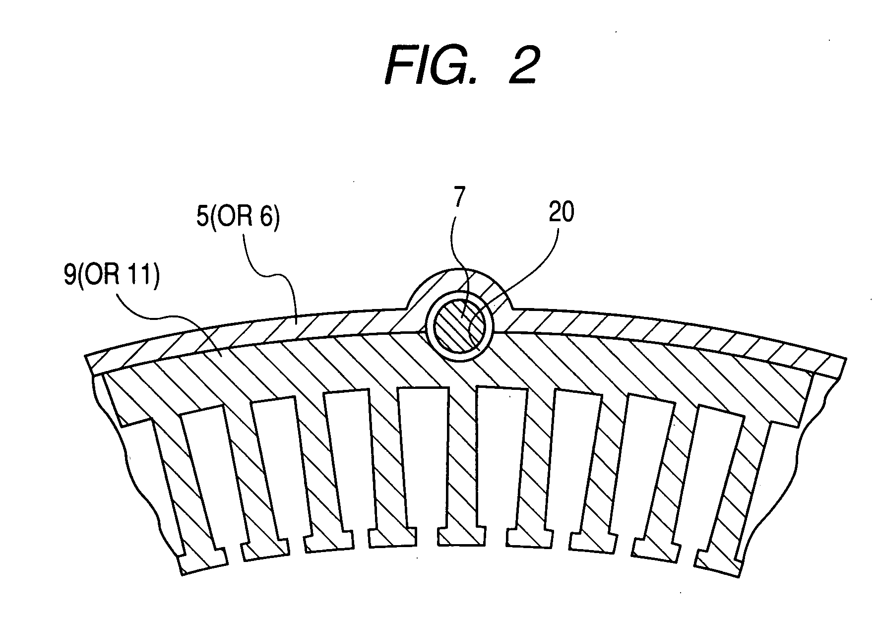
[0046]A plurality of bolts 7 are provided to tightly connect the front and rear housings 5 and 6 together. More specifically, as shown in FIG. 1, each of the bolts 7 extends in the axial direction of t...

second embodiment

[0069]This embodiment illustrates an automotive tandem alternator 200 which has a structure almost identical to that of the alternator 100 according to the previous embodiment. Accordingly, only the differences therebetween will be described hereinafter.

[0070]Referring again to FIG. 1, in the alternator 100, the axial widths (i.e., the widths in the axial direction of the rotary shaft 2) of the outside and inside disc portions 12A and 12B of the field core 12 are equal to each other, and the axial widths of the inside and outside disc portions 14A and 14B of the field core 14 are also equal to each other. Accordingly, the sum of axial widths of the inside disc portions 12B and 14A are equal to that of the outside disc portions 12A and 14B.

[0071]In comparison, referring to FIGS. 3 and 4, in the alternator 200, both the axial widths of the inside disc portions 12B and 14A are reduced, so that the sum of axial widths of the inside disc portions 12B and 14A is less than that of the outs...

third embodiment

[0078]This embodiment illustrates an automotive tandem alternator 300 which has a structure almost identical to that of the alternator 200 according to the second embodiment. Accordingly, only the differences therebetween will be described hereinafter.

[0079]Referring again to FIG. 4, in the alternator 200, the inside disc portion 12B of the field core 12 and the inside disc portion 14A of the field core 14 are separately formed. Further, each of the claw portions 102 of the field core 12 extending from the inside disc portion 12B is aligned in the axial direction of the rotary shaft 2 with one of the claw portions 103 of the field core 14 extending from the inside disc portion 14A. In other words, the circumferential position (i.e., the position in the circumferential direction of the rotary shaft 2) of each of the claw portions 102 coincides with that of one of the claw portions 103.

[0080]In comparison, referring to FIG. 5, in the alternator 300, the inside disc portion 12B of the ...


PUM


Abstract

According to the invention, a tandem alternator includes a rotary shaft, a first and a second field arranged in tandem on the rotary shaft, and a first and a second armature arranged in tandem in the axial direction of the rotary shaft. The first armature is provided on an outer periphery of the first field to constitute a first power generation unit. The second armature is provided on an outer periphery of the second field to constitute a second power generation unit. The first and second fields are arranged to abut each other in the axial direction of the rotary shaft, so as to minimize the axial length of the alternator. The first and second fields are configured to respectively create a first and a second magnetomotive force whose directions are opposite to each other, so as to minimize magnetic leakage between the first and second power generation units.

Description

CROSS-REFERENCE TO RELATED APPLICATION[0001]This application is based on and claims priority from Japanese Patent Application No. 2006-110985, filed on Apr. 13, 2006, the content of which is hereby incorporated by reference into this application.BACKGROUND OF THE INVENTION[0002]1. Technical Field of the Invention[0003]The present invention relates generally to electric generators. More particularly, the invention relates to a tandem alternator for a vehicle, which has a reduced length in the axial direction of a rotary shaft thereof and can effectively suppress magnetic leakage between power generation units arranged in tandem in the axial direction.[0004]2. Description of the Related Art[0005]A conventional tandem alternator 500 for a vehicle includes, as shown in FIG. 6, a single rotary shaft 501 and two power generation units 502 and 503 that are arranged in tandem in the axial direction of the rotary shaft 501.[0006]The power generation unit 502 includes a field 502A and an arma...

Claims


Application Information

Patent Timeline
IPC IPC(8): H02K16/02H02K1/06
CPCH02K1/243H02K19/22H02K16/00
Inventor KUSASE, SHINMAEKAWA, TAKEOSHICHIJOH, AKIYA
Owner DENSO CORP
Why Eureka
Try Eureka