Shipping and display container

a shipping and display container technology, applied in the field of corrugated shipping and display containers, can solve the problems of limited removable sections, difficult manufacturing and burdensome use, and limited nature and type of products that may be placed in the container

Active Publication Date: 2012-10-09
INT PAPER CO
View PDF7 Cites 12 Cited by
  • Summary
  • Abstract
  • Description
  • Claims
  • Application Information

AI Technical Summary

Benefits of technology

[0006]In a preferred embodiment the front wall is formed of a first front wall panel integral with the top wall and a second front wall panel integral with the bottom wall, said first and second front wall panels each having a side flap extending into said side wall and being secured together only by attachment of said side flaps with side flaps on the top and bottom walls, respectively. The first frangible means comprises a tear-out panel integral with the top wall and extending from a rear edge of the top wall and into the back wall. In a preferred embodiment the tear-out panel has a width less than the width of the top wall where the tear-out panel joins it, leaving short connecting portions at opposite sides of the tear-out panel between the rear edge of the top wall and the top edge of the back wall. A third frangible means extends across each connecting portion so that upon removal of the tear-out panel and breaking of the third frangible means the top wall can be completely separated from the back wall. It should be understood that where the tear-out panel joins the top wall it could have a width substantially the same as the width of the top wall, or it could have substantially less width, as desired. The second frangible means comprises a line of perforations connecting together the side flaps on the first and second front wall panels, wherein the top, part of the back and most of the front of the container can be quickly and easily completely removed by the single step of grasping and tearing out the tear-out panel and lifting the tear-out panel to pivot the top upwardly, breaking the lines of perforations in the side walls that connect the first and second front wall panels together. Further, the manner of folding and gluing the panels in the container of the invention produces uninterrupted flat surfaces on all sides for accepting graphics.

Problems solved by technology

Such structure is difficult to manufacture and burdensome to use.
Further, containers with limited removable sections restrict access to the products within the container.
Thus, the nature and type of product that may be placed in the container is limited.
Moreover, the manner of folding and gluing the blank results in a triple thickness of flaps at the sides of the container, and produces interrupted surfaces on the sides of the container that make it difficult to apply graphics to those surfaces.

Method used


Image

  • Shipping and display container
  • Shipping and display container
  • Shipping and display container

Examples


first embodiment

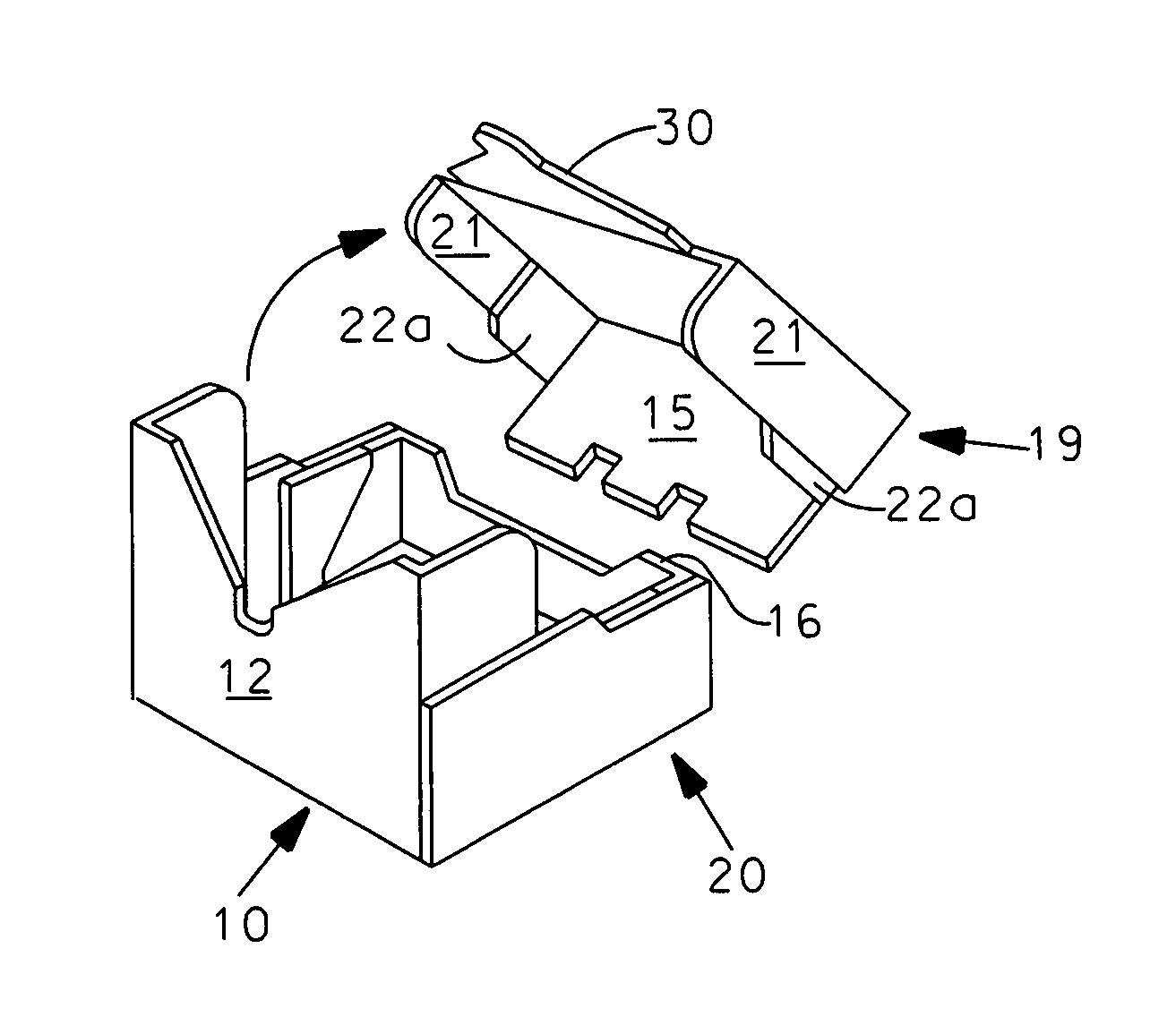
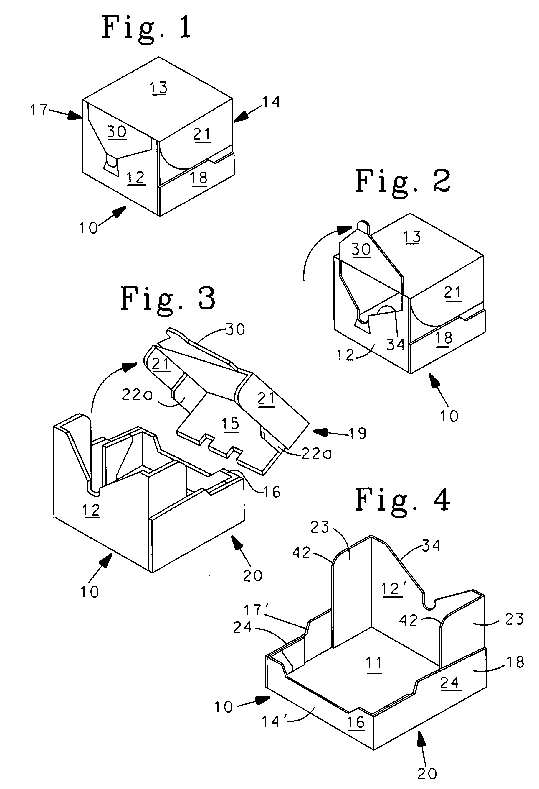
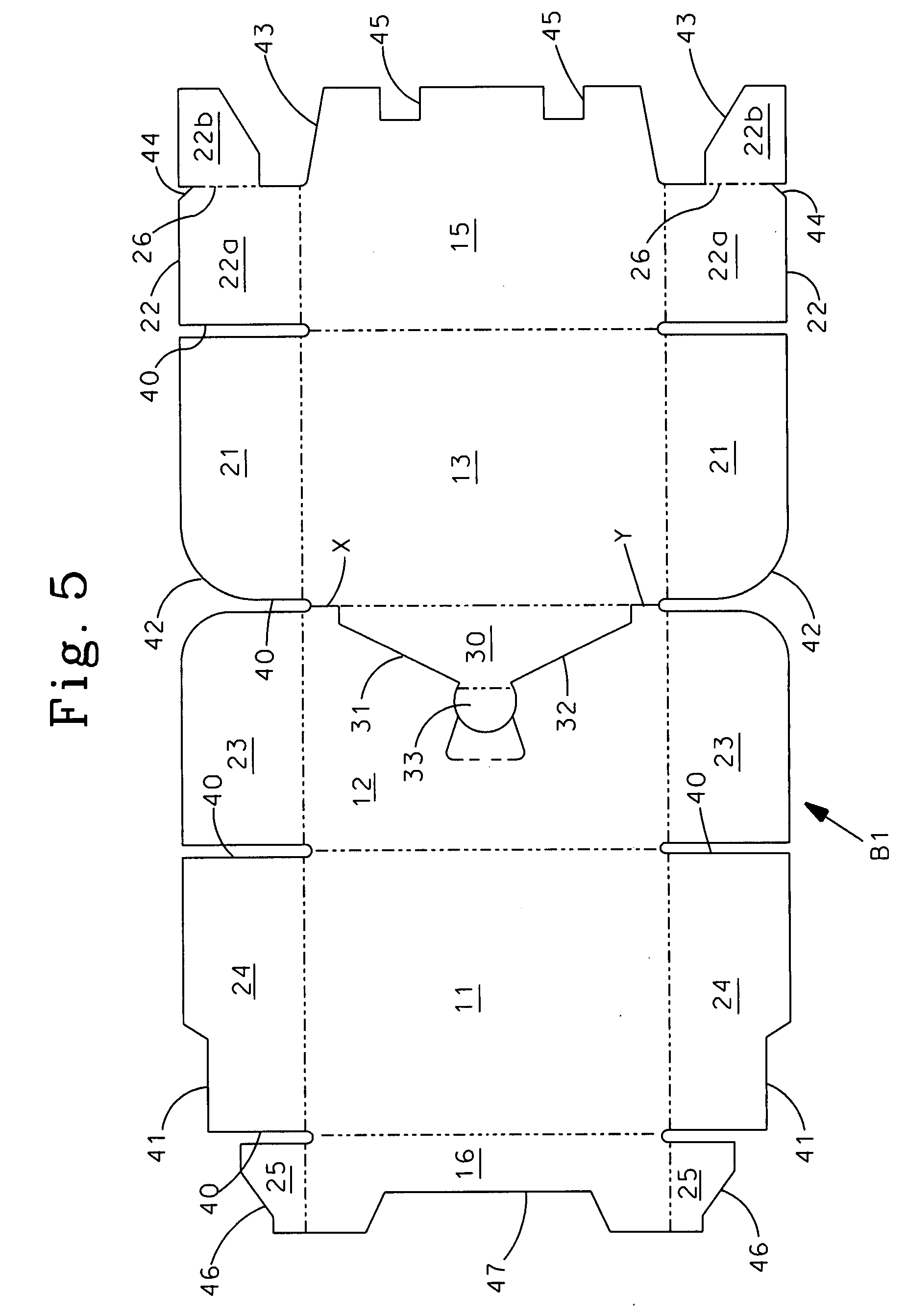
[0028]A blank B1 is illustrated in FIG. 5 for making container having an outside major front wall panel, as shown for example in FIGS. 1-4. The blank comprises a single piece of corrugated material cut and scored to form bottom, back, and top wall panels 11, 12, and 13, respectively, extending consecutively along the length of the blank, and major and minor front wall panels 15 and 16, respectively, at opposite ends of the blank. The major front wall panel 15 has a height from its connection with the top wall panel 13 to its free edge substantially the same as the height of the back wall panel 12, and the minor front wall panel has a substantially smaller height.

[0029]A first pair of side flaps 21 is foldably joined to opposite ends of the top wall panel, a second pair of side flaps 22 is foldably joined to opposite ends of the major front wall panel, a third pair of side flaps 23 is foldably joined to opposite ends of the back wall panel, a fourth pair of side flaps 24 is foldably ...

second embodiment

[0035]A blank B2 for making container according to the invention is illustrated in FIG. 6. This form of the invention is substantially the same as the first embodiment, except that the cut outs 43′ are smaller and shaped differently than the cuts 43 in the first embodiment, whereby the second portions 22b′ of the second side flaps 22′ are sized and shaped differently and the frangible line 26′ is longer than the line 26 in the first embodiment. The cuts 46′ in the outer free edges of the fifth side flaps 25′ are shaped differently so that these side flaps are shaped differently than the side flaps 25 in the first embodiment. Otherwise, the structure and function and method of assembly and erection of this second embodiment are essentially the same as the first embodiment.

third embodiment

[0036]A blank B3 for making container according to the invention is illustrated in FIG. 7. The bottom, back and top wall panels 11, 12 and 13, respectively, and their associated side flaps in this form of the invention are essentially the same as in the previous embodiments, except that the corner of the side flaps 21′ extending from the top wall panel is cut off at an angle 42′ rather than rounded as in the previous embodiments. The major differences in this embodiment are in the shapes of the major and minor front wall panels and the side flaps extending therefrom, and the way in which the blank is folded and glued. Thus, with reference to FIG. 7 and FIGS. 7a-7i, the cut-outs 43″ produce rounded corners 52 on the free edge of the major front wall panel 15′, and the second portions 22b″ of the second flaps 22″ are rectangular in shape, having nearly the same width as the first portions 22a″. The V-shaped cuts 44′ at the outer ends of the frangible lines 26 are also deeper than in t...


PUM


Abstract

A container and a blank for making it. The container is constructed from a single sheet of foldable material and has a bottom wall, a top wall, first and second front wall panels, a back wall, and side flaps extending from opposite ends of the bottom, top, and back walls, and from the first and second front wall panels. The top wall is secured to the container by a tear-out panel extending from the top wall into the back wall and by frangible side flap portions in the side walls, whereby the tear-out panel may be grasped and lifted to lift the top wall and break the frangible side flap portions, completely freeing the top wall from the container by the single step of grasping and tearing out and lifting the tear-out panel to pivot the top upwardly. A blank and method of assembling and erecting the blank to form the container also are disclosed.

Description

FIELD OF INVENTION[0001]This invention relates generally to containers and to blanks for making them. More specifically, the invention relates to a corrugated shipping and display container and to a blank for making it, wherein the container is easy to open and provides easy access to the contents when it is open.BACKGROUND OF THE INVENTION[0002]Many products are shipped in containers having a portion that can be removed at a point of use or sale to display the product in the container and make the product easily accessible. These containers typically have a top portion that can be partially or wholly removed or pivoted out of the way to expose the contents. Containers with removable top portions generally use tear tapes or the like to facilitate the separation of the top portion from the bottom portion. Such structure is difficult to manufacture and burdensome to use. Further, containers with limited removable sections restrict access to the products within the container. Thus, the...

Claims


Application Information

Patent Timeline
Patent Type & Authority Patents(United States)
IPC IPC(8): B65D79/00B65D5/02
CPCB65D5/5445
Inventor FODEN, ROY D. P.
Owner INT PAPER CO
Why Eureka
Try Eureka