
Design of a path connecting a first point to a second point in a three-dimensional scene

a three-dimensional scene and design technology, applied in the field of computer programs and systems, can solve the problems of not helping the designer to select the right path quickly, designer cannot check the clash with the context with the right precision, and existing solutions suffer from several drawbacks

Active Publication Date: 2015-01-29
DASSAULT SYSTEMES
View PDF9 Cites 16 Cited by
  • Summary
  • Abstract
  • Description
  • Claims
  • Application Information

AI Technical Summary

Benefits of technology

The invention provides a computer-implemented method for designing a path connecting two points in a three-dimensional scene using a parallelepiped. The method involves orienting the parallelepiped in the scene, providing a bend radius for connecting at least two portions of the path, computing a new position of the vertices based on the bend radius and the angle between the vectors, and determining the length of each edge of the path. The invention also provides a computer program and a computer-aided design system for implementing the method. The technical effect of the invention is to provide a more efficient and precise method for designing paths in three-dimensional scenes.

Problems solved by technology

However, the existing solutions suffer of several drawbacks.
First, they do not help the designer to select the right path quickly with the right input.
In particular, in the event the solution is only a line, the designer cannot check with right precision the clash with the context.
In addition, it can take time for the designer to review all solutions because the solutions are show one by one.
Moreover, impossible solutions are shown: an impossible solution is a solution that is not realistic.
For instance, an air ducts route following three portions of a same wall is considered as being an impossible solution because such a solution is unrealistic in the real world.

Method used


Image

  • Design of a path connecting a first point to a second point in a three-dimensional scene
  • Design of a path connecting a first point to a second point in a three-dimensional scene
  • Design of a path connecting a first point to a second point in a three-dimensional scene

Examples


Embodiment Construction

[0045]A description of example embodiments of the invention follows.

[0046]The teachings of all patents, published applications and references cited herein are incorporated by reference in their entirety.

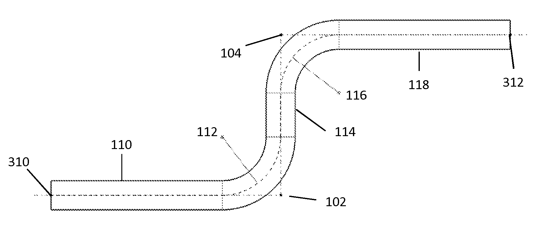
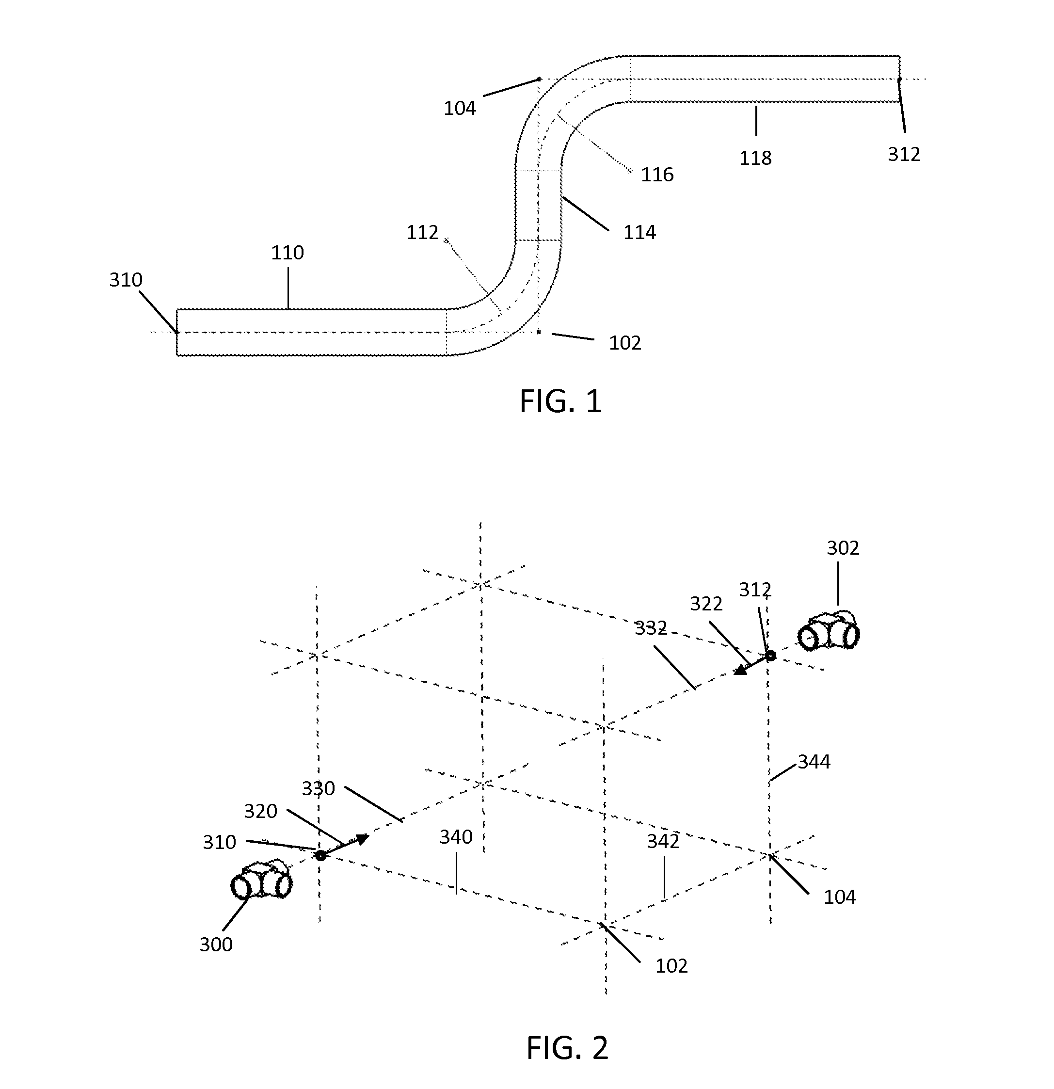
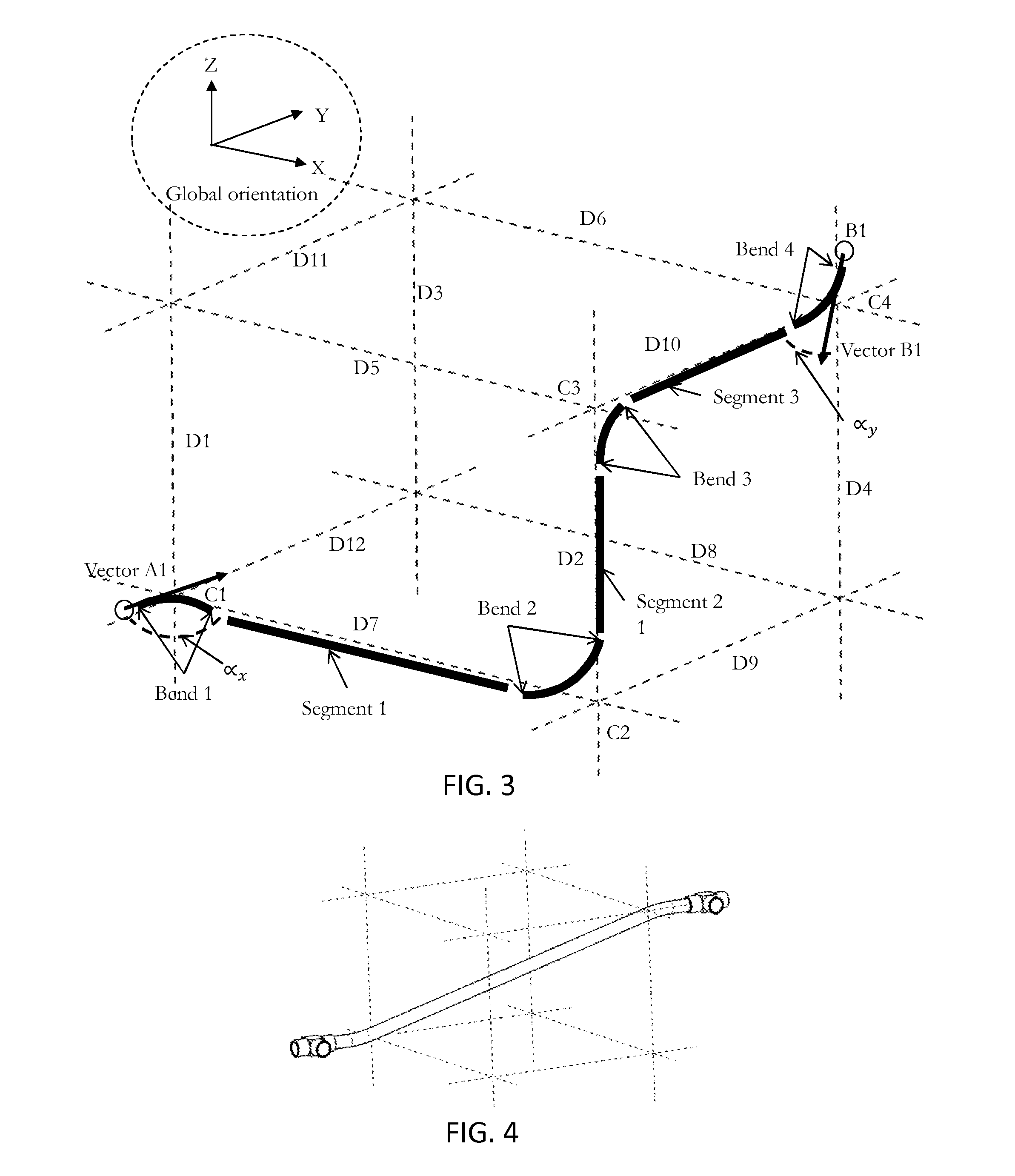
[0047]With reference to the flowcharts of FIGS. 26 to 28, it is proposed a computer-implemented method for designing a path connecting a first point to a second point in a three-dimensional scene. A path is a set of points connected by, but not limited to, straight line, arcs, curves . . . . A path may be represented by a polyline (also referred to as polygonal chain) that comprises a connected series of line segments. The set of points comprises at least two points, namely a first point and a second point. The first point may be also referred to as start point and the second point may be also referred to as end point. The method comprises providing a first point coupled with a first vector and providing the second point coupled with a second vector. A vector is a geometric object th...


PUM


Abstract

It is proposed a computer-implemented method, system and program product designing a path connecting a first point to a second point in a three-dimensional scene. The method comprises:providing the first point coupled with a first vector;providing the second point coupled with a second vector; andproviding a set of paths by following at the most three portions of a parallelepiped, the parallelepiped comprising the provided first point on a first vertex and the provided second point on a second vertex, a portion of the parallelepiped being an edge, a diagonal of a face, a space diagonal.

Description

RELATED APPLICATION(S)[0001]This application claims priority under 35 U.S.C. §119 or 365 to Europe, Application No. 13306081.4, filed Jul. 25, 2013. The entire teachings of the above application(s) are incorporated herein by reference.FIELD OF THE INVENTION[0002]The invention relates to the field of computer programs and systems, and more specifically to a method, computer-aided system and computer program for designing a path connecting a first point to a second point in a three-dimensional scene.BACKGROUND OF THE INVENTION[0003]A number of systems and programs are offered on the market for the design, the engineering and the manufacturing of objects. CAD is an acronym for Computer-Aided Design, e.g. it relates to software solutions for designing an object. CAE is an acronym for Computer-Aided Engineering, e.g. it relates to software solutions for simulating the physical behavior of a future product. CAM is an acronym for Computer-Aided Manufacturing, e.g. it relates to software so...

Claims


Application Information

Patent Timeline
IPC IPC(8): G06T19/00
CPCG06T2215/06G06T19/003G06F30/17G06F30/18G06F2113/16G06F2113/14G06F30/13
Inventor LEREY, GUILLAUME
Owner DASSAULT SYSTEMES
Learn More