Apparatus for receiving and transmitting optical information

a technology for optical information and apparatus, applied in the field of optical information transmitting and receiving apparatus, can solve the problems of inaccurate reading limited amount of information stored in information symbols, and inability to accurately read information, so as to improve data transmission efficiency and large capacity data

Active Publication Date: 2015-01-29
SAMSUNG ELECTRONICS CO LTD
View PDF8 Cites 36 Cited by
  • Summary
  • Abstract
  • Description
  • Claims
  • Application Information

AI Technical Summary

Benefits of technology

[0013]When the optical information transmitting apparatus is used as an alternative of an information symbol such as a QR code (please refer to FIG. 1A), the relatively larger capacity data when compared to the conventional information symbol such as the QR code (please refer to FIG. 1A) may be directly transmitted.
[0014]Also, data desired to be transmitted in real time may be variously modified and corrected as necessary and thus, efficiency of data transmission may be improved.

Problems solved by technology

Therefore, the optical information reading device may cause a problem in that information stored in an information symbol is wrongly read.
Also, when a symbol that is directly marked on a metal surface of a product through direct marking is read, the mirror reflection may frequently occur and thus, information stored in an information symbol may not be accurately read.
Also, an amount of information that the information symbol may store is limited and thus, the information symbol generally links address information of a place where large capacity information is stored.
Therefore, it is inappropriate that the large capacity information is directly transmitted using the information symbol.
Also, the information symbol stores only information formed during a process that produces the symbol, and has a drawback in that additional information is not added to the formed information symbol or the information symbol is not corrected.

Method used


Image

  • Apparatus for receiving and transmitting optical information
  • Apparatus for receiving and transmitting optical information
  • Apparatus for receiving and transmitting optical information

Examples


Embodiment Construction

[0025]Hereinafter, various embodiments of the present invention will be described with reference to the accompanying drawings. Further, various specific definitions found in the following description are provided only to help general understanding of the present invention, and it is apparent to those skilled in the art that the present invention can be implemented without such definitions.

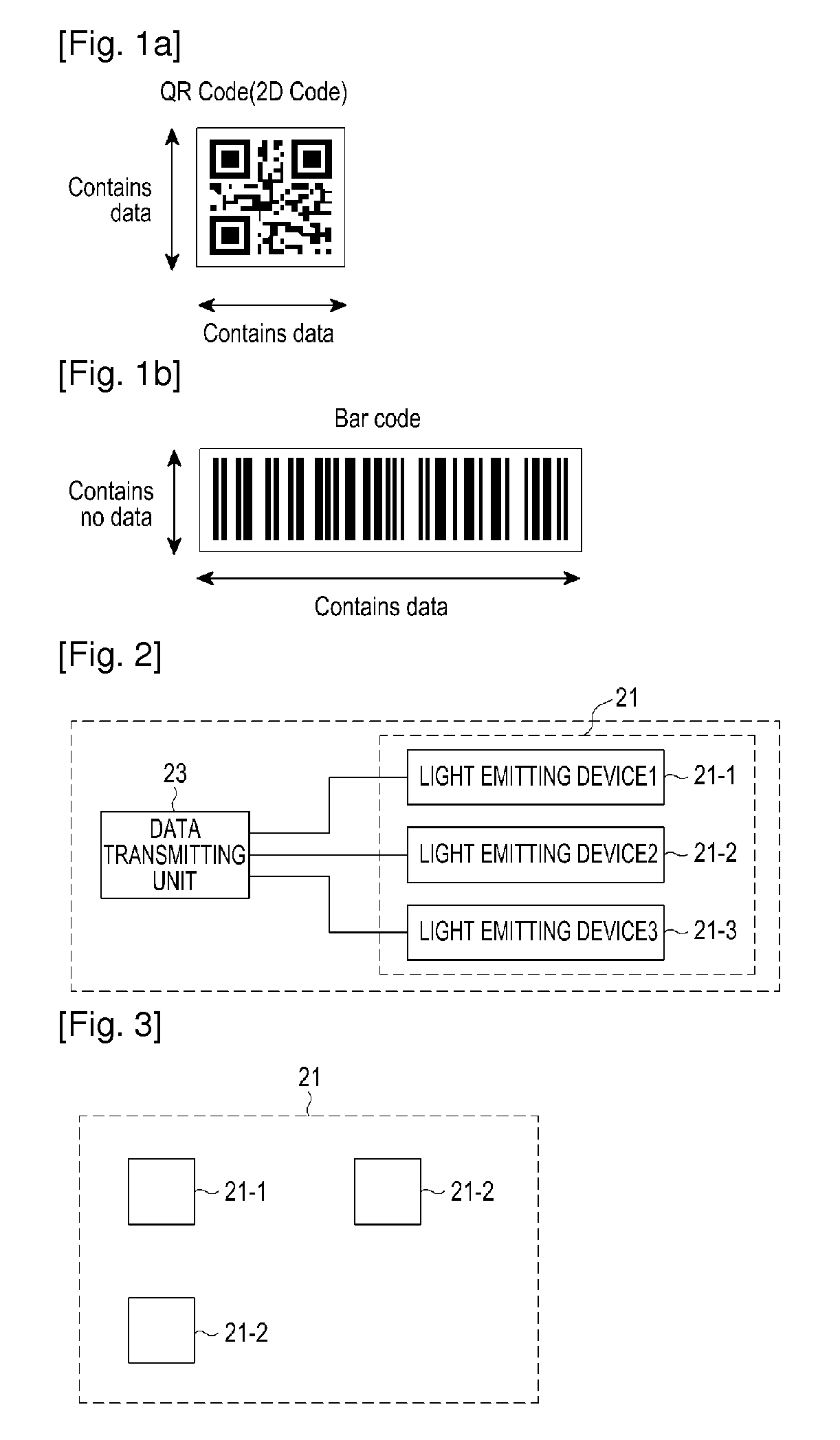
[0026]FIG. 2 illustrates a configuration of an optical information transmitting apparatus according to an embodiment of the present invention. Referring to FIG. 2, the optical information transmitting apparatus includes at least three light emitting devices 21, and a data transmitting unit 23 to transmit data by controlling the at least three light emitting devices 21.

[0027]Each light emitting device is installed based on a predetermined interval and direction. For example, referring to FIG. 3 that illustrates a predetermined interval and direction of each light emitting device, the light emitting ...


PUM


Abstract

An apparatus for transmitting information using a visible light includes at least three light emitting devices, each being installed based on a predetermined interval and direction, and a data transmitting unit to transmit data by controlling the at least three light emitting devices.

Description

TECHNICAL FIELD[0001]The present invention relates generally to a visible light communication technology, and more particularly, to an optical information transmitting and receiving apparatus using visible light communication.BACKGROUND ART[0002]An optical information reading device is well known that optically reads an information symbol, such as a QR code (please refer to FIG. 1A), a barcode (please refer to FIG. 1B), and the like, attached on a product and a document.[0003]The optical information reading device is configured of a small body case including a reading window provided in its one end, a light detector such as a Charge-Coupled Device (CCD) sensor, an imaging unit including an imaging lens, and a lighting device such as a Light Emitting Diode (LED), and the light detector, the imaging unit, and the lighting device are installed in the body case.[0004]When a user desires to read an optical symbol attached on a product using the configuration of the optical information re...

Claims


Application Information

Patent Timeline
Patent Type & Authority Applications(United States)
IPC IPC(8): H04B10/116G06V30/224
CPCH04B10/116G06K7/10H04B10/11G06V30/224
Inventor SON, JAE-SEUNGPARK, SEUNG-HOONBAE, TAE-HANWON, EUN-TAE
Owner SAMSUNG ELECTRONICS CO LTD
Why Eureka
Try Eureka