Reinforced non-pneumatic tire and system for molding reinforced non-pneumatic tire

a non-pneumatic tire, non-pneumatic technology, applied in the direction of heavy duty tyres, dough shaping, food shaping, etc., can solve the problems of passengers' discomfort, non-pneumatic tires may be relatively heavy, and not have the ability to provide the desired level of cushioning,

Inactive Publication Date: 2015-02-05
CATERPILLAR INC
View PDF26 Cites 26 Cited by
  • Summary
  • Abstract
  • Description
  • Claims
  • Application Information

AI Technical Summary

Problems solved by technology

However, non-pneumatic tires may suffer from a number of possible drawbacks.
For example, non-pneumatic tires may be relatively heavy and may not have a sufficient ability to provide a desired level of cushioning.
For example, some non-pneumatic tires may provide little, if any, cushioning, potentially resulting in discomfort to passengers and / or damage to cargo.
In addition, some non-pneumatic tires may not be able to maintain a desired level of cushioning when the load changes on the tire.
In particular, if the structure of the non-pneumatic tire provides the desired level of cushioning for a given load, it may not be able to continue to provide the desired level of cushioning if the load is changed.
Moreover, for non-pneumatic tires that provide an acceptable level of cushioning, the radial compliance of the tires may result in exceeding the stress and strain limits of the material used to form the tires.
Exceeding the stress or strain limits of the material may lead to cracking or a reduced service life of the tire.
Although the cushioned tire disclosed in the '844 patent provides cushioning, it may suffer from a number of drawbacks sometimes associated with non-pneumatic tires.
For example, the tire disclosed in the '844 patent may not be able to maintain a desired level of cushioning when the load on the tire changes.
In addition, achieving the desired level of cushioning may result in exceeding the stress and strain limits of the material forming the tire.

Method used


Image

  • Reinforced non-pneumatic tire and system for molding reinforced non-pneumatic tire
  • Reinforced non-pneumatic tire and system for molding reinforced non-pneumatic tire
  • Reinforced non-pneumatic tire and system for molding reinforced non-pneumatic tire

Examples


Embodiment Construction

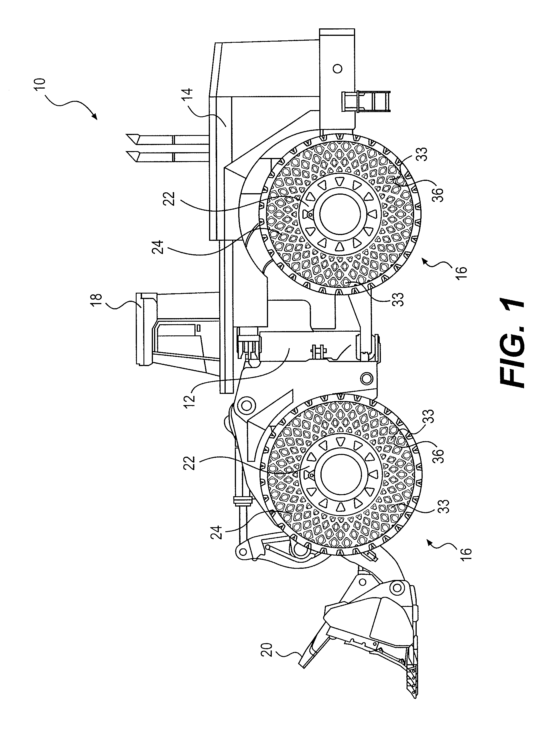
[0017]FIG. 1 shows an exemplary machine 10 configured to travel across terrain. Exemplary machine 10 shown in FIG. 1 is a wheel loader. However, machine 10 may be any type of ground-borne vehicle, such as, for example, an automobile, a truck, an agricultural vehicle, and / or a construction vehicle, such as, for example, a dozer, a skid-steer loader, an excavator, a grader, an on-highway truck, an off-highway truck, and / or any other vehicle type known to a person skilled in the art. In addition to self-propelled machines, machine 10 may be any device configured to travel across terrain via assistance or propulsion from another machine.

[0018]Exemplary machine 10 shown in FIG. 1 includes a chassis 12 and a powertrain 14 coupled to and configured to supply power to wheels 16, so that machine 10 is able to travel across terrain. Machine 10 also includes an operator station 18 to provide an operator interface and protection for an operator of machine 10. Machine 10 also includes a bucket 2...


PUM

PropertyMeasurementUnit
inner diameteraaaaaaaaaa

Abstract

A non-pneumatic tire may include an inner circumferential portion configured to be coupled to a hub, and an outer circumferential portion radially spaced from the inner circumferential portion. The tire may further include a support structure extending between the inner circumferential portion and the outer circumferential portion and coupling the inner circumferential portion to the outer circumferential portion. The support structure may at least partially define a first axial side of the tire and a second axial side of the tire opposite the first axial side of the tire. The support structure may have a plurality of cavities at least partially extending between the first axial side of the tire and the second axial side of the tire, and at least some of the cavities may be reinforced with a synthetic reinforcing material.

Description

TECHNICAL FIELD[0001]The present disclosure relates to tires and systems for molding tires, and more particularly, to reinforced non-pneumatic tires and systems for molding reinforced non-pneumatic tires.BACKGROUND[0002]Machines such as vehicles, either self-propelled or pushed or pulled, often include wheels for facilitating travel across terrain. Such wheels often include a tire to protect a rim or hub of the wheel, provide cushioning for improved comfort or protection of passengers or cargo, and provide enhanced traction via a tread of the tire. Non-pneumatic tires have been used for machines as an alternative to pneumatic tires. Non-pneumatic tires may be relatively less complex than pneumatic tires because they do not retain air under pressure. However, non-pneumatic tires may suffer from a number of possible drawbacks. For example, non-pneumatic tires may be relatively heavy and may not have a sufficient ability to provide a desired level of cushioning. For example, some non-p...

Claims


Application Information

Patent Timeline
Patent Type & Authority Applications(United States)
IPC IPC(8): B60C7/10B29C70/84
CPCB29C70/84B60C7/10B60C2007/107B60C2007/005B29D30/02B60C2200/065B60C7/107B60C7/146
Inventor MARTIN, KEVIN L.
Owner CATERPILLAR INC
Why Eureka
Try Eureka