Dental Extraction Burs for Extraction of a tooth or a portion of a Tooth

a technology of tooth extraction and tooth burs, which is applied in the field of dental extraction, can solve the problems of inadvertent fracture of tooth crowns, increased trauma to patients, and significant damage to adjacent tissue, and achieve the effect of minimizing soft and hard tissue damag

Inactive Publication Date: 2015-02-05
ORR LARRY EUGENE +1
View PDF15 Cites 6 Cited by
  • Summary
  • Abstract
  • Description
  • Claims
  • Application Information

AI Technical Summary

Benefits of technology

[0006]The disclosed present invention uses various extraction burs to complete the tooth or portion of tooth extraction in a matter of minutes; while minimizing soft and hard tissue damage. In one case, implementation begins when the practitioner uses a drill to make a hole in the tooth or portion of tooth. The drill provides a resultant hole that is sized correctly to accept the Extraction Bur.

Problems solved by technology

Crowns of the teeth can be inadvertently fractured due to physical trauma or because of complications during tooth extraction procedures by practitioners.
Now the practitioner is faced with causing increased trauma to the patient in order to remove these tooth remnants.
Present art uses either rudimental and unsophisticated tools which cause trauma to soft and hard tissue or more sophisticated devices whose expense makes them prohibitive for a typical practitioner The rudimental tools are used to loosen the tooth or portion of the tooth, elevate it and then remove it with forceps.
This procedure can cause significant damage to adjacent tissue.
In some cases, a substantial amount of force is required which exacerbates the already difficult situation.
If the practitioner is working near a sinus cavity, there is a danger that the root tip can be inadvertently driven into it.
However, these screw or screw-like devices have limited success due to the splitting nature of screws or breakage of the device itself due to the inherent weakness when it is made sufficiently small so it can be screwed into the nerve canal.
Even with skill and experience, this procedure can lead to a decrease in patient satisfaction; an increased in healing time due to jaw bone loss, blood vessel and nerve damage; loss of time for the practitioner & patient and re-scheduling issues, thereby reducing productivity of the practice.

Method used


Image

  • Dental Extraction Burs for Extraction of a tooth or a portion of a Tooth
  • Dental Extraction Burs for Extraction of a tooth or a portion of a Tooth
  • Dental Extraction Burs for Extraction of a tooth or a portion of a Tooth

Examples


Embodiment Construction

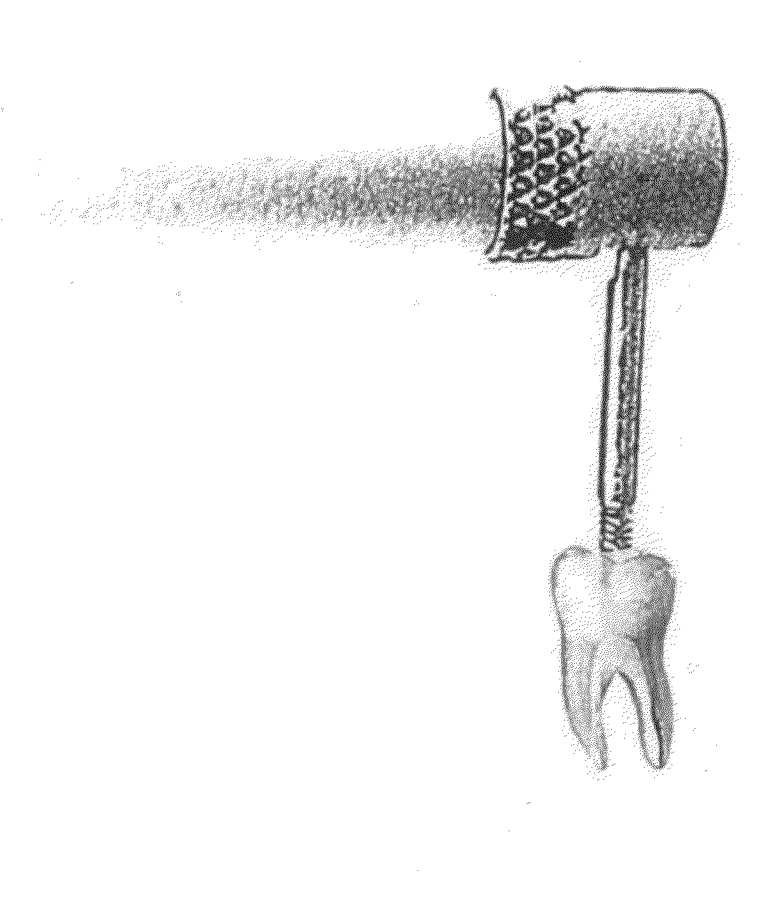
[0018]In this detail, we use the word tooth to describe either a tooth or portion of tooth.

[0019]We have derived a number of Extraction Burs that can be used to remove a tooth. Fundamentally they can be divided into two groups. In case one, the Extraction Bur is embedded in a hole. In case two, the Extraction Bur is attached to the surface of the tooth.

[0020]Case one begins when a drill is locked in the practitioner's slow speed hand piece and used to create a hole in the tooth. Drills are sized to provide a hole that allows the Extraction Bur maximum engagement with the tooth.

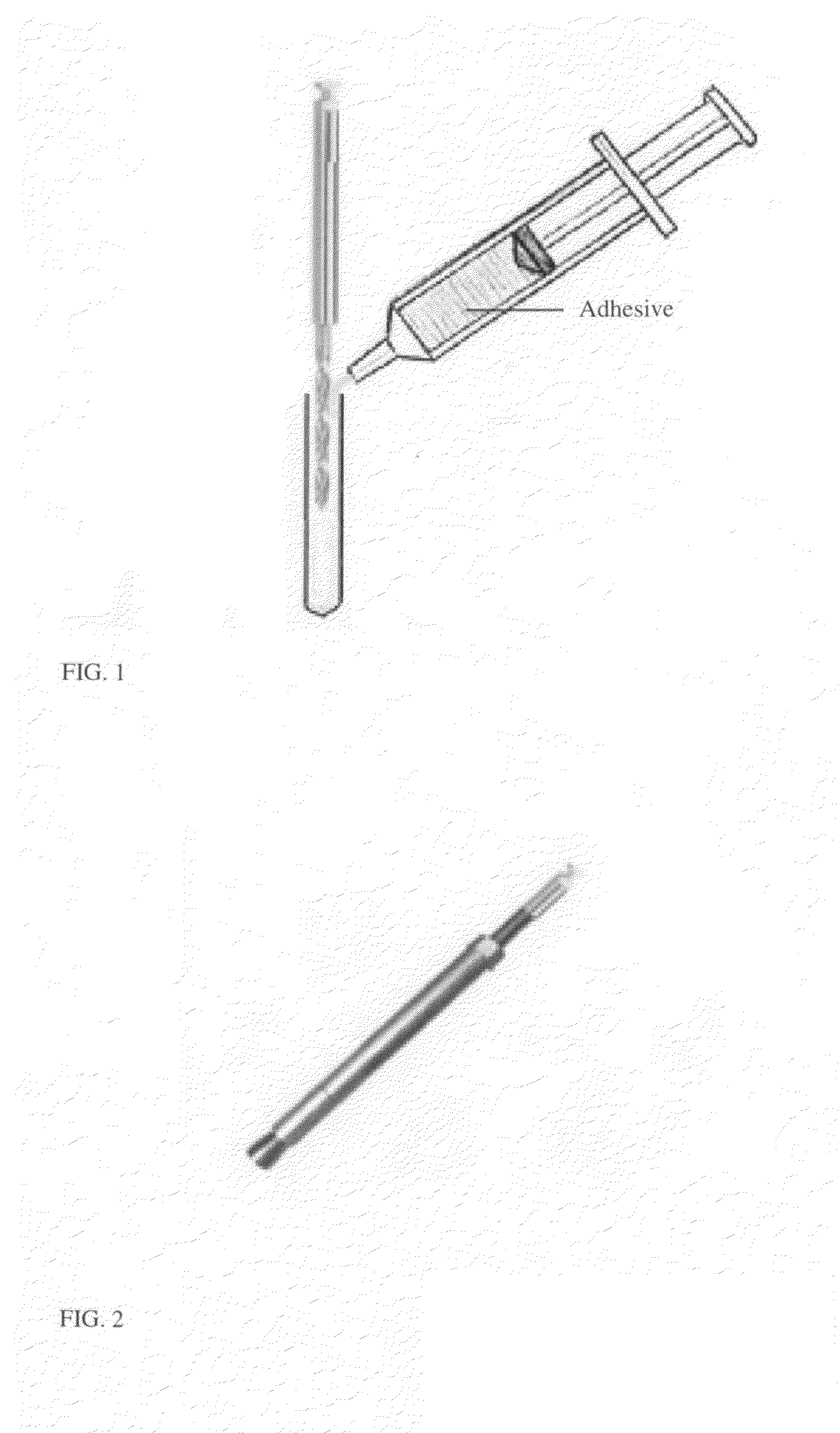
[0021]FIG. 1 illustrates and Extraction Bur which uses the drill as the Extractor. Once the hole is established, the drill can be removed from the slow speed hand piece and cleaned. Then using an adhesive to coat the drill, it is re-inserted in the hole. When the drill is bonded to the tooth, the practitioner attached the handle to the drill and uses it to luxate the tooth / remove it.

[0022]FIG. 2 illustrates an...


PUM


Abstract

Various Dental Extraction Burs are provided to practitioners to assist them in the extraction of a tooth or a portion of a tooth. Some Extraction Burs are embedded in a hole drilled in the tooth or portion of tooth, while others are attached to the surface of the tooth. After the Extraction Bur is attached to the tooth, the practitioner secures a handle to the Extraction Bur. Using the handle, the Extraction Bur and tooth or portion of tooth is removed from the patient.

Description

THE FIELD OF THE INVENTION[0001]The present invention generally relates to the field of dentistry and more particularly to the extraction of a tooth or a portion of a tooth from humans or animals.THE BACKGROUND ART OF THE INVENTION[0002]Crowns of the teeth can be inadvertently fractured due to physical trauma or because of complications during tooth extraction procedures by practitioners. If this occurs, the root(s) or root tip(s) usually remain in the jaw. Now the practitioner is faced with causing increased trauma to the patient in order to remove these tooth remnants.[0003]Present art uses either rudimental and unsophisticated tools which cause trauma to soft and hard tissue or more sophisticated devices whose expense makes them prohibitive for a typical practitioner The rudimental tools are used to loosen the tooth or portion of the tooth, elevate it and then remove it with forceps. This procedure can cause significant damage to adjacent tissue. Often the practitioner must excav...

Claims


Application Information

Patent Timeline
Patent Type & Authority Applications(United States)
IPC IPC(8): A61C3/02
CPCA61C3/02A61C1/12A61C3/14
Inventor LUZZADER, WAYNE RICHARDORR, LARRY EUGENE
Owner ORR LARRY EUGENE
Why Eureka
Try Eureka