
Transmitter apparatus and signal processing method thereof

a technology of transmitter apparatus and signal processing method, which is applied in the direction of digital transmission, code conversion, coding, etc., to achieve the effect of improving decoding and receiving performan

Active Publication Date: 2015-02-05
SAMSUNG ELECTRONICS CO LTD
View PDF7 Cites 165 Cited by
  • Summary
  • Abstract
  • Description
  • Claims
  • Application Information

AI Technical Summary

Benefits of technology

The patent text describes various ways to improve how data is decoded and received in a system. These improvements can lead to better performance and overall better performance of the system.

Problems solved by technology

However, it is understood that one or more exemplary embodiment are not required to overcome the disadvantages described above, and may not overcome any of the problems described above.

Method used


Image

  • Transmitter apparatus and signal processing method thereof
  • Transmitter apparatus and signal processing method thereof
  • Transmitter apparatus and signal processing method thereof

Examples


exemplary embodiment 1

Use of Block Interleaver

[0130]According to a first exemplary embodiment, the interleaver 120 may interleave the LDPC codeword in a method described below such that a bit included in a predetermined group from among a plurality of groups constituting the interleaved LDPC codeword is mapped onto a predetermined bit in a modulation symbol. A detailed description thereof is provided with reference to FIG. 4.

[0131]FIG. 4 is a block diagram to illustrate a configuration of an interleaver according to exemplary embodiment. Referring to FIG. 4, the interleaver 120 includes a parity interleaver 121, a group interleaver (or a group-wise interleaver 122), a group twist interleaver 123 and a block interleaver 124.

[0132]The parity interleaver 121 interleaves parity bits constituting the LDPC codeword.

[0133]Specifically, when the LDPC codeword is generated based on the parity check matrix 200 having the configuration of FIG. 2, the parity interleaver 121 may interleave only the parity bits of the...

exemplary embodiment 2

Use of Block-Row Interleaver

[0421]According to another exemplary embodiment, the interleaver 120 may interleave an LDPC codeword in other methods, different from the methods described in the exemplary embodiment 1 beginning at paragraph [0127] above, and may map bits included in a predetermined group from among a plurality of groups constituting the interleaved LDPC codeword onto a predetermined bit of a modulation symbol. This will be explained in detail with reference to FIG. 23.

[0422]Referring to FIG. 23, the interleaver 120 includes a parity interleaver 121, a group interleaver (or a group-wise interleaver 122), a group twist interleaver 123 and a block-row interleaver 125. Herein, the parity interleaver 121 and the group twist interleaver 123 perform the same functions as in the exemplary embodiment 1 described above. and thus, a detailed description of these elements is omitted.

[0423]The group interleaver 122 may divide a parity-interleaved LDPC codeword into a plurality of gr...


PUM


Abstract

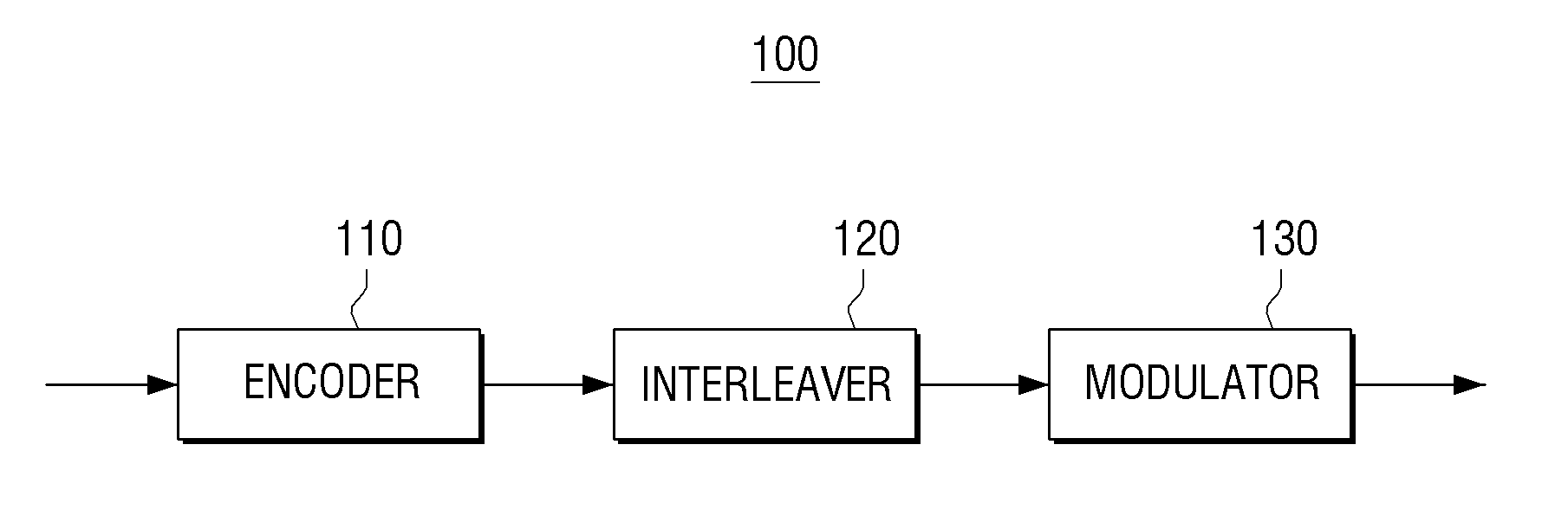
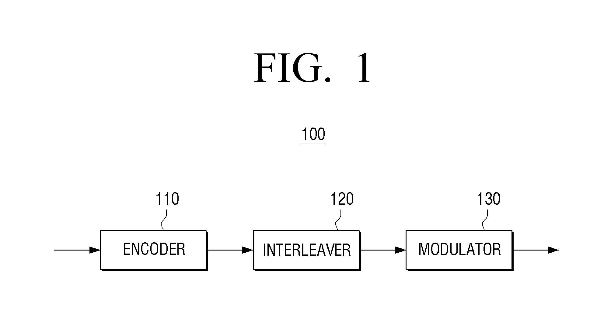
A transmitter apparatus and a receiver apparatus are provided. The transmitter apparatus includes: an encoder configured to generate a low density parity check (LDPC) by performing LDPC encoding; an interleaver configured to interleave the LDPC codeword; and a modulator configured to map the interleaved LDPC codeword onto a modulation symbol. The modulator maps a bit included in a predetermined group from among a plurality of groups constituting the LDPC codeword onto a predetermined bit in the modulation symbol.

Description

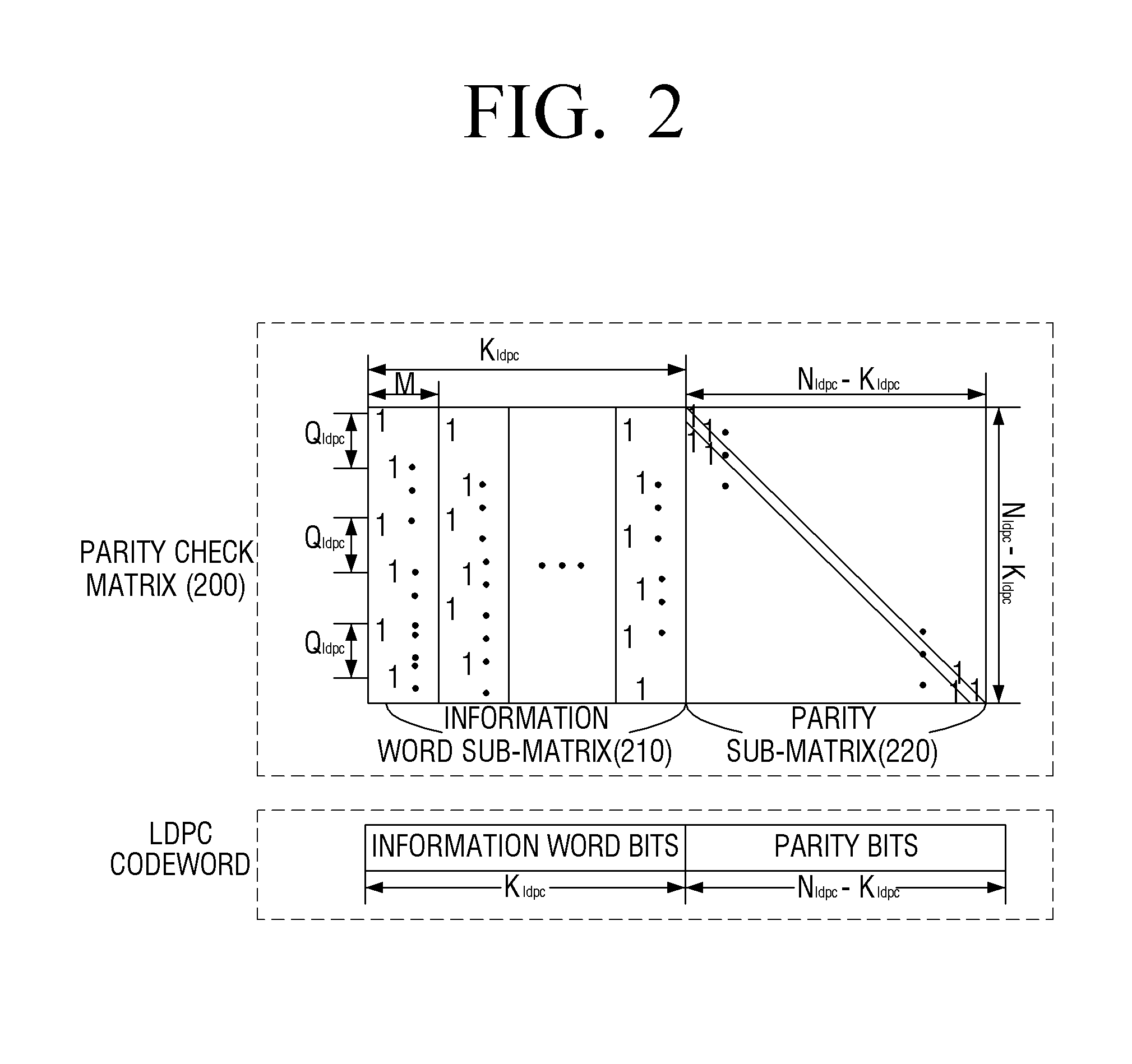
CROSS-REFERENCE TO RELATED APPLICATION(S)[0001]This application claims the benefit under 35 U.S.C. §119 from U.S. Provisional Application No. 61 / 843,114 filed on Jul. 5, 2013, U.S. Provisional Application No. 61 / 864,758 filed on Aug. 12, 2013, U.S. Provisional Application No. 61 / 878,707 field on Sep. 17, 2013, U.S. Provisional Application No. 61 / 882,724 filed on Sep. 26, 2013, U.S. Provisional Application No. 61 / 886,827 filed on Oct. 4, 2013, and U.S. Provisional Application No. 61 / 897,480 filed on Oct. 30, 2013, in the United States Patent and Trademark Office, and Korean Patent Application No. 10-2013-0125664 filed on Oct. 21, 2013, Korean Patent Application No. 10-2014-0026298 filed on Mar. 5, 2014, and Korean Patent Application No. 10-2014-0083647 filed on Jul. 4, 2014, in the Korean Intellectual Property Office, the disclosure of which is incorporated herein by reference in its entirety.BACKGROUND[0002]1. Technical Field[0003]Apparatuses and methods consistent with exemplary em...

Claims


Application Information

Patent Timeline
IPC IPC(8): H03M13/27H03M13/11H04L1/00H04L27/04
CPCH03M13/2792H04L1/004H03M13/1102H04L27/04H03M13/1165H03M13/255H03M13/271H03M13/356H04L1/0041H04L1/0057H04L27/36H03M13/2778H04L1/0071H03M13/27H03M13/11H04L1/00H03M13/1177H03M13/616H03M13/6538H03M13/6552H03M13/6555
Inventor JEONG, HONG-SILMYUNG, SE-HOKIM, KYUNG-JOONG
Owner SAMSUNG ELECTRONICS CO LTD
Learn More