
Circuit for driving power switch, power supply apparatus and method for driving power switch

Inactive Publication Date: 2015-02-12
SOLUM CO LTD
View PDF12 Cites 7 Cited by
  • Summary
  • Abstract
  • Description
  • Claims
  • Application Information

AI Technical Summary

Benefits of technology

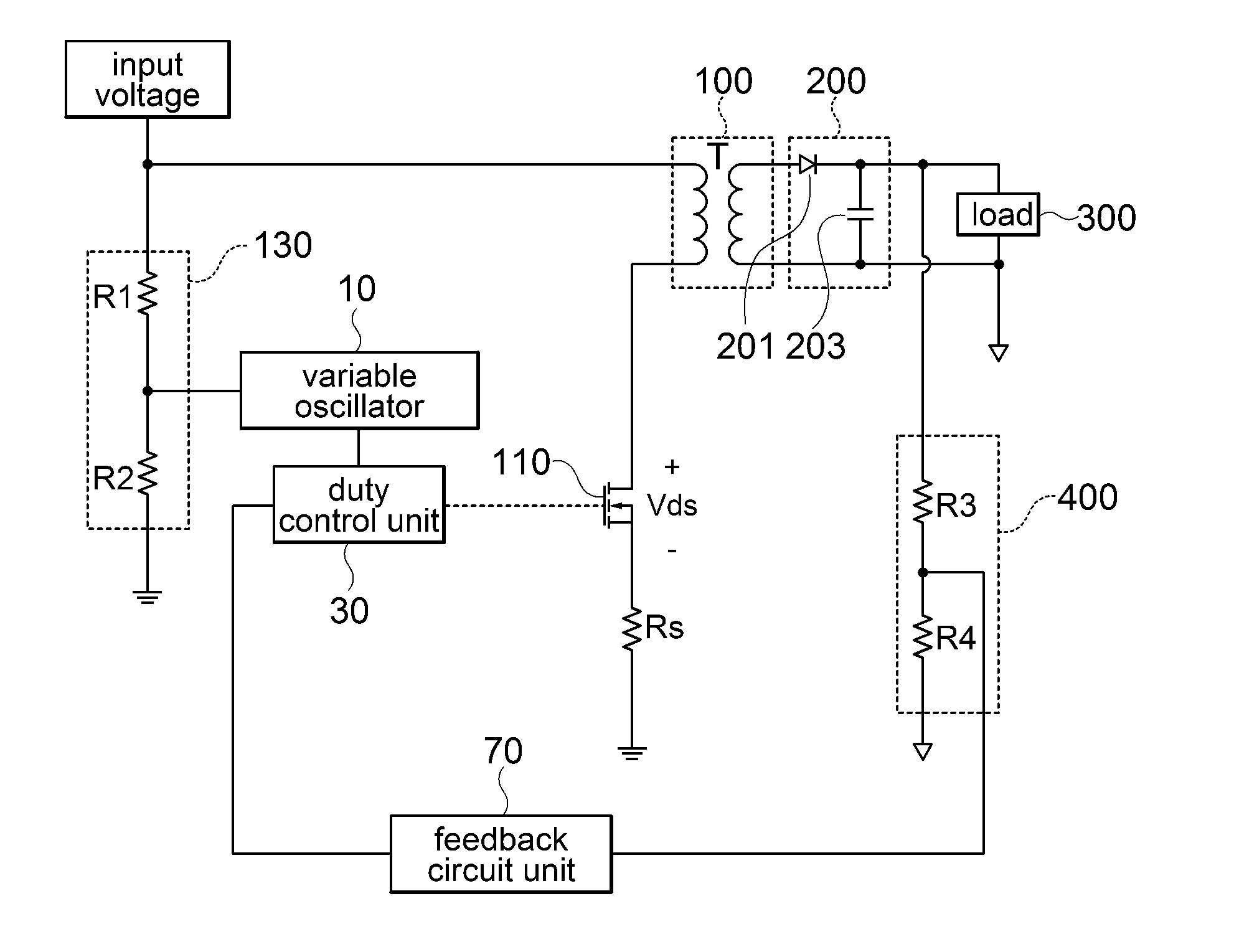
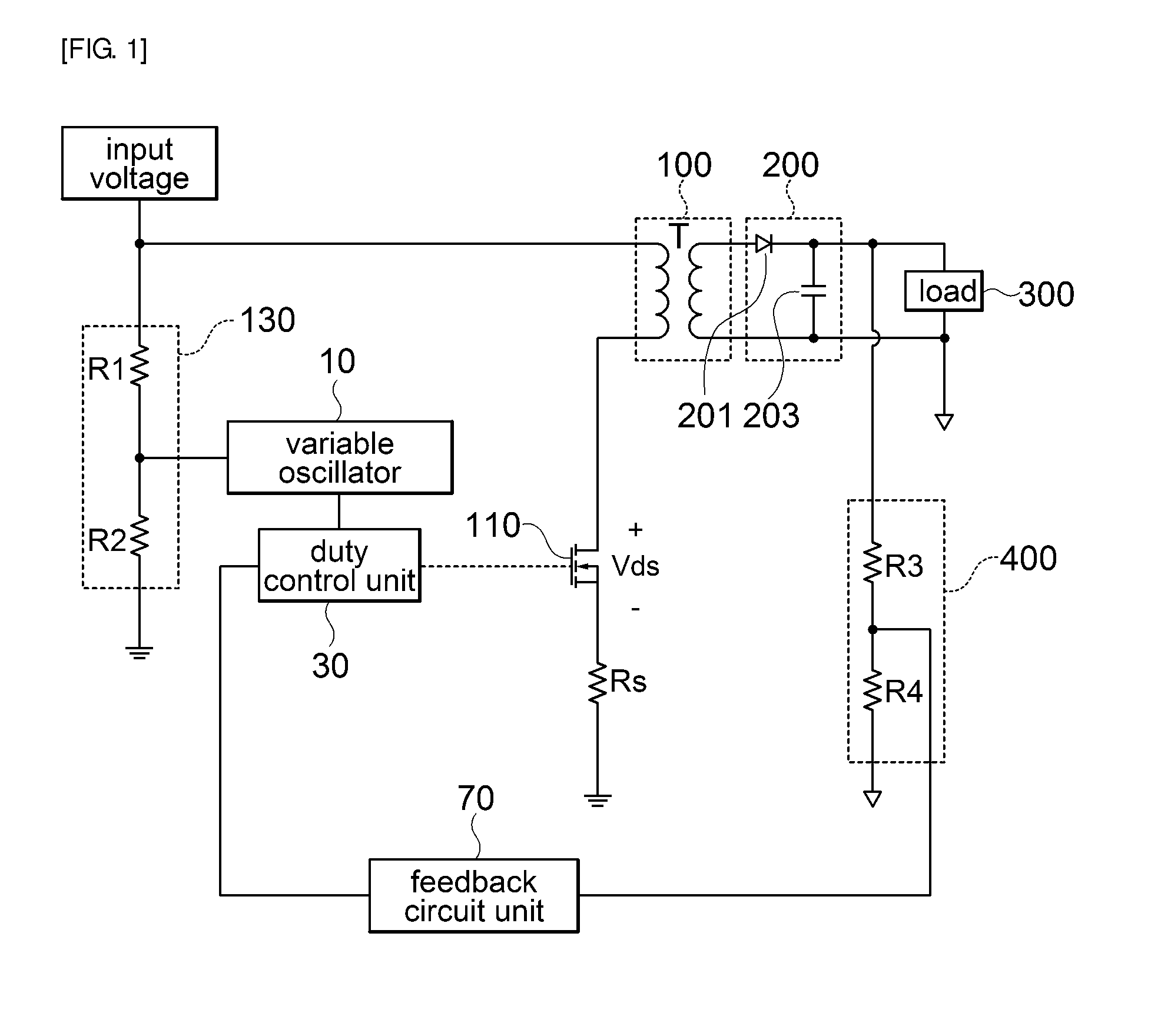
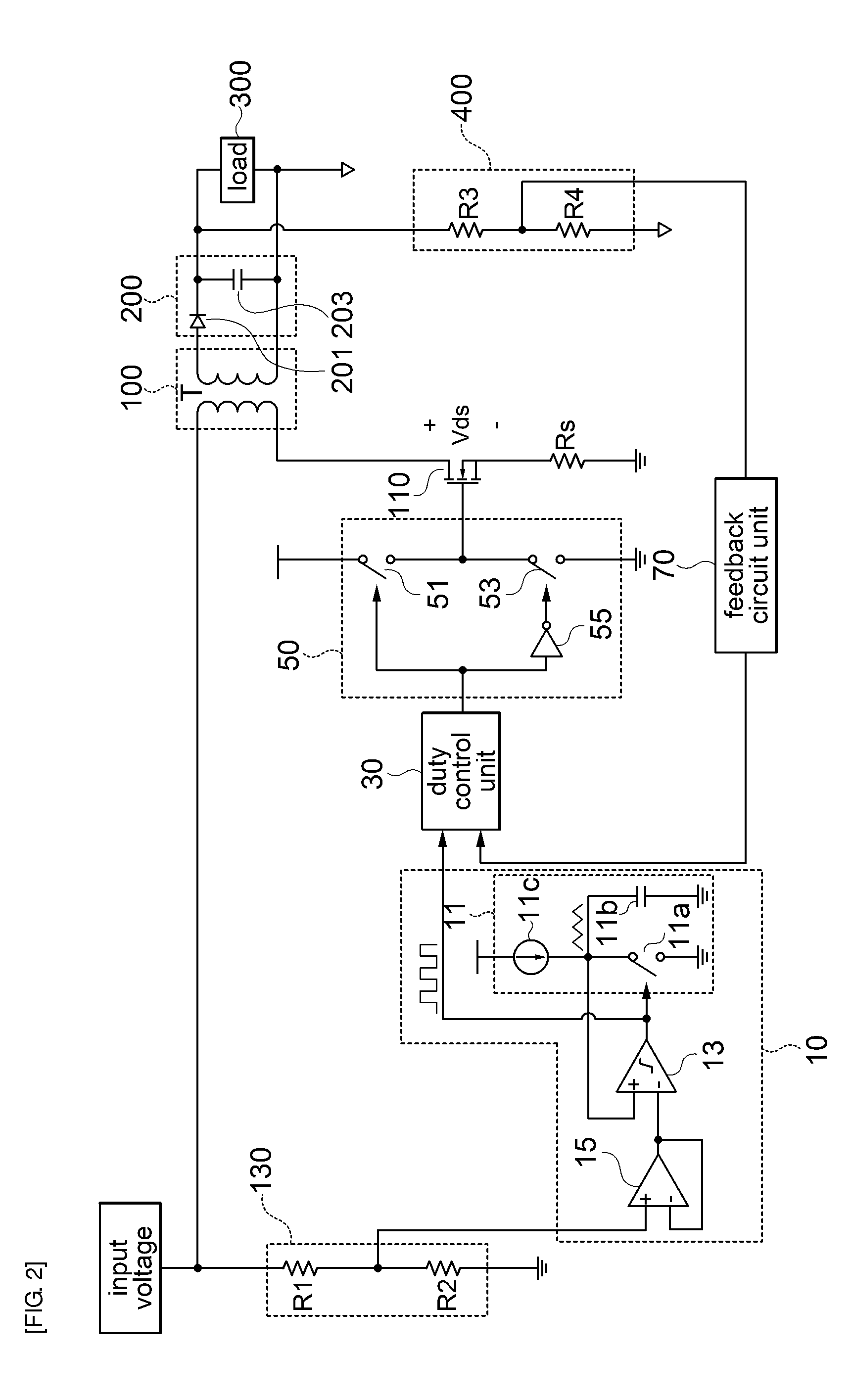
The present invention provides a technology that improves the switching loss of a power switch by adjusting the frequency of a reference signal for duty control of the switch according to the input voltage. A variable oscillator can reduce the frequency of the reference signal when the primary side input voltage increases, which in turn reduces the loss of power during the switching process. This results in improved efficiency of the power switch circuit.

Problems solved by technology

However, since an SMPS has a specific switching frequency according to design characteristics of the system, the frequency cannot be reduced unconditionally to reduce losses.

Method used


Image

  • Circuit for driving power switch, power supply apparatus and method for driving power switch
  • Circuit for driving power switch, power supply apparatus and method for driving power switch
  • Circuit for driving power switch, power supply apparatus and method for driving power switch

Examples


Embodiment Construction

[0034]Embodiments of the present invention to achieve the above-described objects will be described with reference to the accompanying drawings. In this description, the same elements are represented by the same reference numerals, and additional description which is repeated or limits interpretation of the meaning of the invention may be omitted.

[0035]In this specification, when an element is referred to as being “connected or coupled to” or “disposed in” another element, it can be “directly” connected or coupled to or “directly” disposed in the other element or connected or coupled to or disposed in the other element with another element interposed therebetween, unless it is referred to as being “directly coupled or connected to” or “directly disposed in” the other element.

[0036]Although the singular form is used in this specification, it should be noted that the singular form can be used as the concept representing the plural form unless being contradictory to the concept of the ...


PUM


Abstract

The present invention relates to a circuit for driving power switch, a power supply apparatus, and a method for driving a power switch. According to an embodiment of the present invention, a circuit for driving power switch, which includes a variable oscillator for varying a frequency according to a change in primary side input voltage to output a reference signal for duty control; and a duty control unit for receiving a feedback signal fed back from a secondary side output signal and the reference signal for duty control from the variable oscillator and outputting a duty control signal for driving a power switch, is provided. Further, a power supply apparatus and a method for driving a power switch are provided.

Description

CROSS-REFERENCE TO RELATED APPLICATIONS[0001]Claim and incorporate by reference domestic priority application and foreign priority application as follows:“CROSS REFERENCE TO RELATED APPLICATION[0002]This application claims the benefit under 35 U.S.C. Section 119 of Korean Patent Application Serial No. 10-2013-0095417, entitled filed Aug. 12, 2013, which is hereby incorporated by reference in its entirety into this application.”BACKGROUND OF THE INVENTION[0003]1. Field of the Invention[0004]The present invention relates to a circuit for driving power switch, a power supply apparatus, and a method for driving a power switch, and more particularly, to a circuit for driving power switch, a power supply apparatus, and a method for driving a power switch that can vary a frequency of a reference signal for duty control of a power switch according to an input voltage.[0005]2. Description of the Related Art[0006]A switch mode power supply (hereinafter, SMPS) is a device that receives a recti...

Claims


Application Information

Patent Timeline
IPC IPC(8): H02M3/335
CPCH02M3/33553H02M3/33507H02M1/0054Y02B70/10H02M3/28H03K17/06H03K17/687
Inventor CHO, HWANGONG, JUNG CHULKIM, JUNG HYUN
Owner SOLUM CO LTD
Learn More