Terminal block assembly

a terminal block and assembly technology, applied in the direction of electrical apparatus, connection, coupling device connection, etc., can solve the problems of unreliable engagement of the intended connection, the terminal pins show inferior structural strength, and the complexity and cost level of metal spring piece manufacturing, so as to achieve less structural complexity, less likely to deform, and easy and convenient operation

Active Publication Date: 2015-02-12
SWITCHLAB SHANGHAI +1
View PDF17 Cites 33 Cited by
  • Summary
  • Abstract
  • Description
  • Claims
  • Application Information

AI Technical Summary

Benefits of technology

[0013]In view of this, the primary objective of the present invention is to provide a terminal block assembly, which is a combination of a terminal block and a lever member pivotally connected to the terminal block and is less structurally complicated and less likely to deform as compared to the existing terminal block products. The terminal block comprises a main body and a chamber defined by the main body. The chamber receives therein a metal spring piece for in response to the lever member's movement to crimp and electrically connect a leading wire or release the leading wire. A buckle is also installed in chamber such that it is allowed to perform reciprocating movements. The buckle is equipped with a spring that makes the buckle normally engage with the lever member until it receives an operating force that cancel the established engagement. Thereby, the disclosed terminal block assembly is easy and convenient to operate.

Problems solved by technology

One issue about such a terminal block or connecting terminal in terms of structural design and application is that for endowing the curved segment with structural strength sufficient for the engagement with the arms of the terminal pin and thus preventing deformation that degrades the engagement between the metal spring piece and the leading wire over time, the curved segment in practice is made as a U-shaped structure.
However, the specially processed structure can significantly increase the complexity and cost level for manufacturing the metal spring piece.
Another issue about such a terminal block or connecting terminal in terms of structural design and application is that for ensuring good electrical conductivity, the terminal pin is usually made of a metal material containing cooper (e.g. brass or the like) and thus is less rigid.
This makes the terminal pin show inferior structural strength when its arms engage with the curved segment of the metal spring piece.
Particularly, after long-term operation, the arms tend to deform and become unreliable for the intended engagement.
While this problem may be solved by increasing the thickness or area of the arms, the consequent high complexity and costs are adverse to the relevant manufacturers.

Method used


Image

  • Terminal block assembly
  • Terminal block assembly
  • Terminal block assembly

Examples


Embodiment Construction

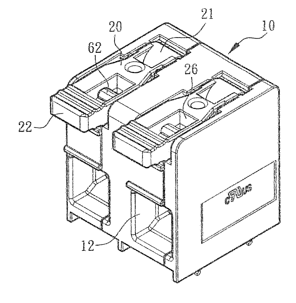
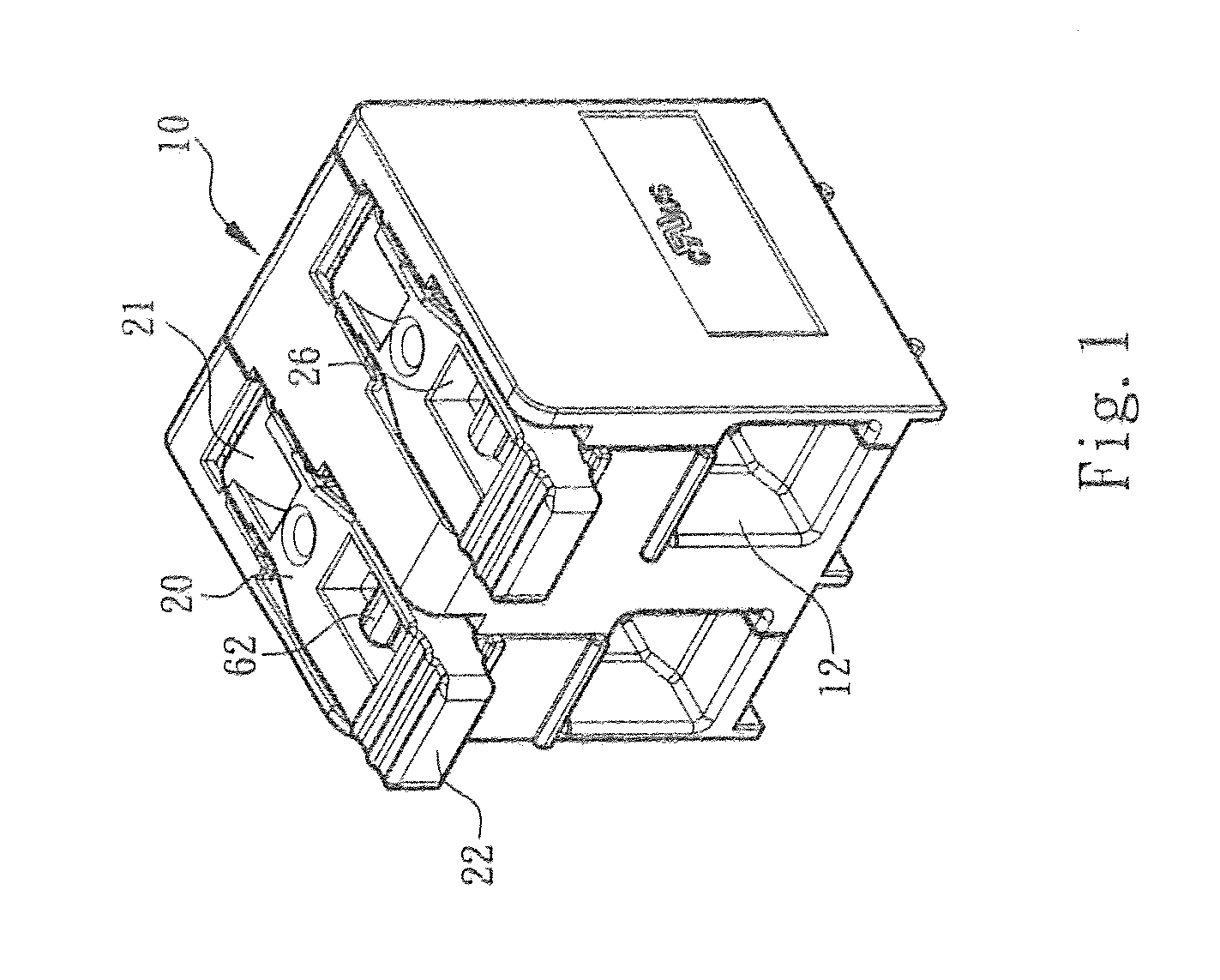
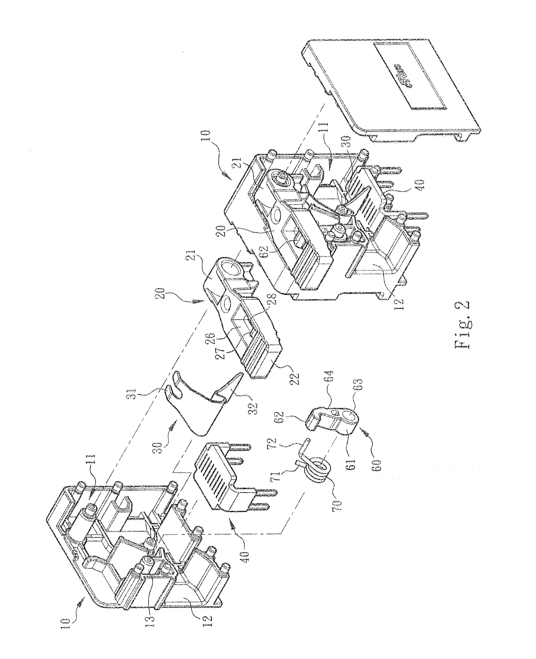
[0023]Referring to FIGS. 1, 2 and 3, according to the present invention, a terminal block assembly comprises a main body made of an insulating material, and a lever member, which are denoted throughout the figures by numerals 10 and 20, respectively. The main body 10 defines therein a chamber 11. The chamber 11 has a metal spring piece 30 and a terminal pin 40 installed therein. The terminal pin 40 is inserted onto a circuit board (e.g. a PUB). The main body 10 also comprises a wire inlet 12 communicated with the chamber 11, so that a leading wire 50 can be inserted into the chamber 11 through the wire inlet 12 and get crimped by the metal spring piece 30, thereby forming electrical connection with the terminal pin 40.

[0024]In the illustrated embodiment, the metal spring piece 30 is configured to move in response to the operation of the lever member 20 to crimp and have electrical connection with the leading wire 50, or release the leading wire 50. Particularly, the lever member 20 ...


PUM


Abstract

A terminal block assembly includes a terminal block and lever member and is less structurally complicated and less likely to deform as compared to the existing terminal block products. The terminal block has a main body and a chamber defined by the main body. The chamber is provided with a metal spring piece, which, in response to movements of the lever member, crimps a leading wire to form electrical connection or release the leading wire. The chamber is also provided with a buckle that performs reciprocating movements and is biased by a spring to normally engage with the lever member. When receiving an operating force, the buckle disengages with the lever member so that the lever member is allowed to move, The terminal block assembly advantageously provides easy and effort-saving operation.

Description

BACKGROUND OF THE INVENTION[0001]1. Technical Field[0002]The present invention relates to wire terminal blocks, and more particularly to a terminal block assembly where electrical leading wires are inserted and connected. The inventive terminal block assembly features for a combination of a lever member, a buckle and a metal spring piece that can be operated in an effort-saving manner to crimp or release a leading wire inserted into the terminal block assembly.[0003]2. Description of Related Art[0004]A terminal (block) or a crimp terminal (block) using a metal piece or a metal spring piece covered by an insulating housing (typically made of plastic) to crimp a leading wire inserted therein and thereby form electrical connection is known.[0005]Such a connecting terminal designed be inserted onto a circuit board (such as a PC circuit board) has an insulating housing that is provided with a through hole or an wire inlet, through which a leading wire can be inserted to the interior of t...

Claims


Application Information

Patent Timeline
Patent Type & Authority Applications(United States)
IPC IPC(8): H01R13/629H01R4/48
CPCH01R4/48H01R13/62933H01R12/515H01R4/48455H01R4/48365H01R12/75
Inventor WU, CHIH-YUANCHEN, WEI-CHILIU, SHIH-CHUNG
Owner SWITCHLAB SHANGHAI
Why Eureka
Try Eureka