
Power transfer device for a rolling door operator

Pending Publication Date: 2021-07-15
ALPINE OVERHEAD DOORS INC
View PDF0 Cites 0 Cited by
  • Summary
  • Abstract
  • Description
  • Claims
  • Application Information

AI Technical Summary

Benefits of technology

The invention is a power transfer device for a rolling door that is easy to operate and can control the speed of the door with different braking mechanisms. It is simple in construction and inexpensive to manufacture. Its technical effects include improved convenience, safety, and flexibility in speed control for rolling doors.

Problems solved by technology

However, when a fire occurred, these mechanisms would disengage the motor from the fire door and allow the door to close under the pressure exerted by an auxiliary spring activated by mechanical means or from a counterbalance.
These mechanical devices tended to be unreliable because of jamming or other malfunctions caused by the motion of the door.
The problem that Shea was attempting to address was the need for a fire door mechanism that regulates the raising and lowering of the door while effectively controlling the door's movement without the need of springs or similar mechanical means.
And, while Fan addresses a legitimate need, it still leaves unanswered the need to allow the door to move freely into an open position while under control of a governor.
A problem left unanswered by Varley is how an operator, under the stress of an emergency, can efficiently disengage the motor drive.
One important issue not addressed by the prior art, is that the drop of the door should be controlled by a mechanical centrifugal governor such that the door does not “bounce” after it arrives in the full open position.
However, the limit switches are mounted inside the motor operator housing and require disassembly of the operator to make any changes or adjustments.
This, however, requires an externally mounted drop arm and an externally mounted plate that can rotate at a relatively high speed, both the drop arm and plate being exposed to contaminants and foreign objects that can interfere with their operation.

Method used


Image

  • Power transfer device for a rolling door operator
  • Power transfer device for a rolling door operator
  • Power transfer device for a rolling door operator

Examples


Embodiment Construction

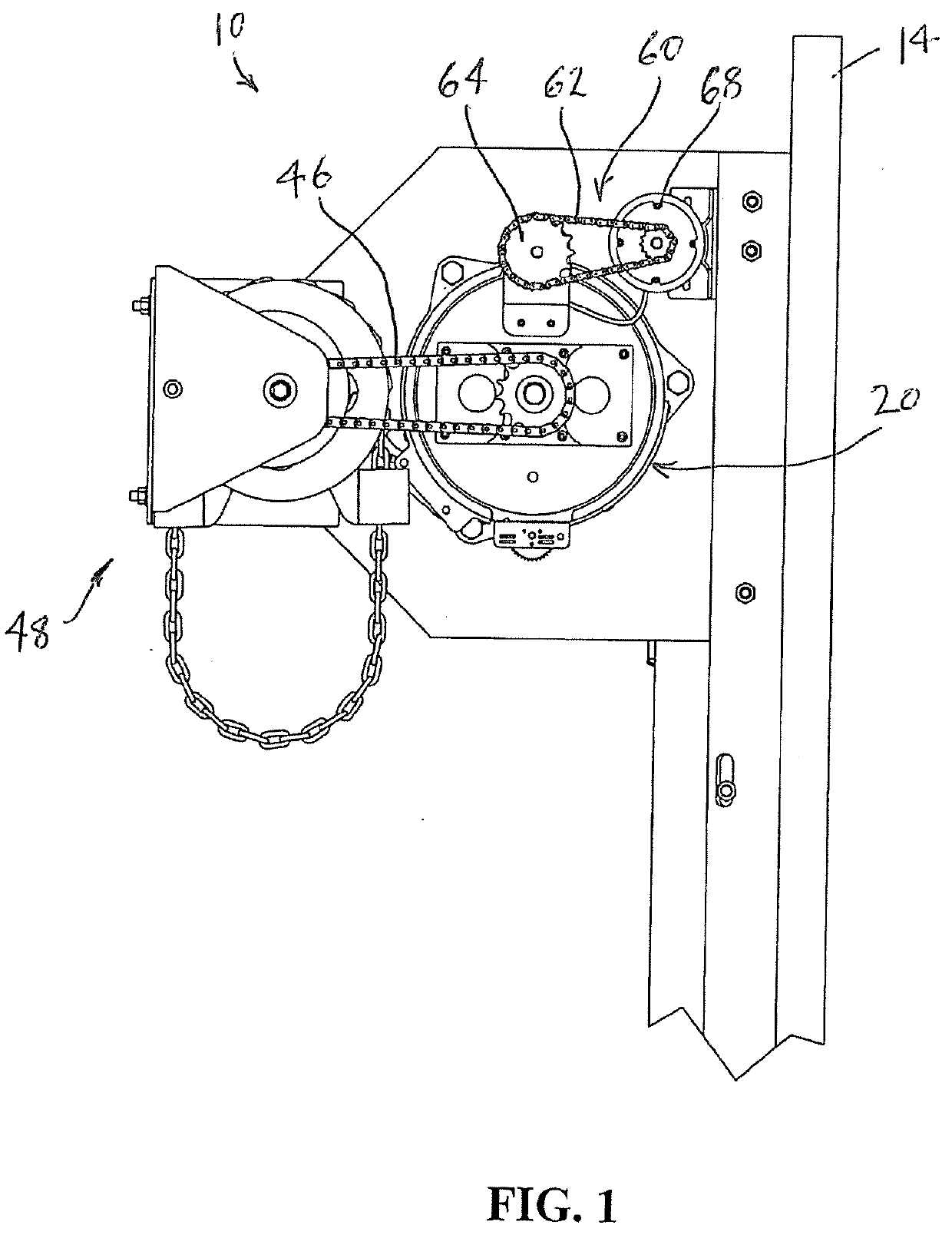
[0034]Referring now to the figures, in which identical or similar parts are designated by the same reference numerals throughout, and first referring to FIG. 1, an operator in accordance with the present invention is generally designated by the reference numeral 10.

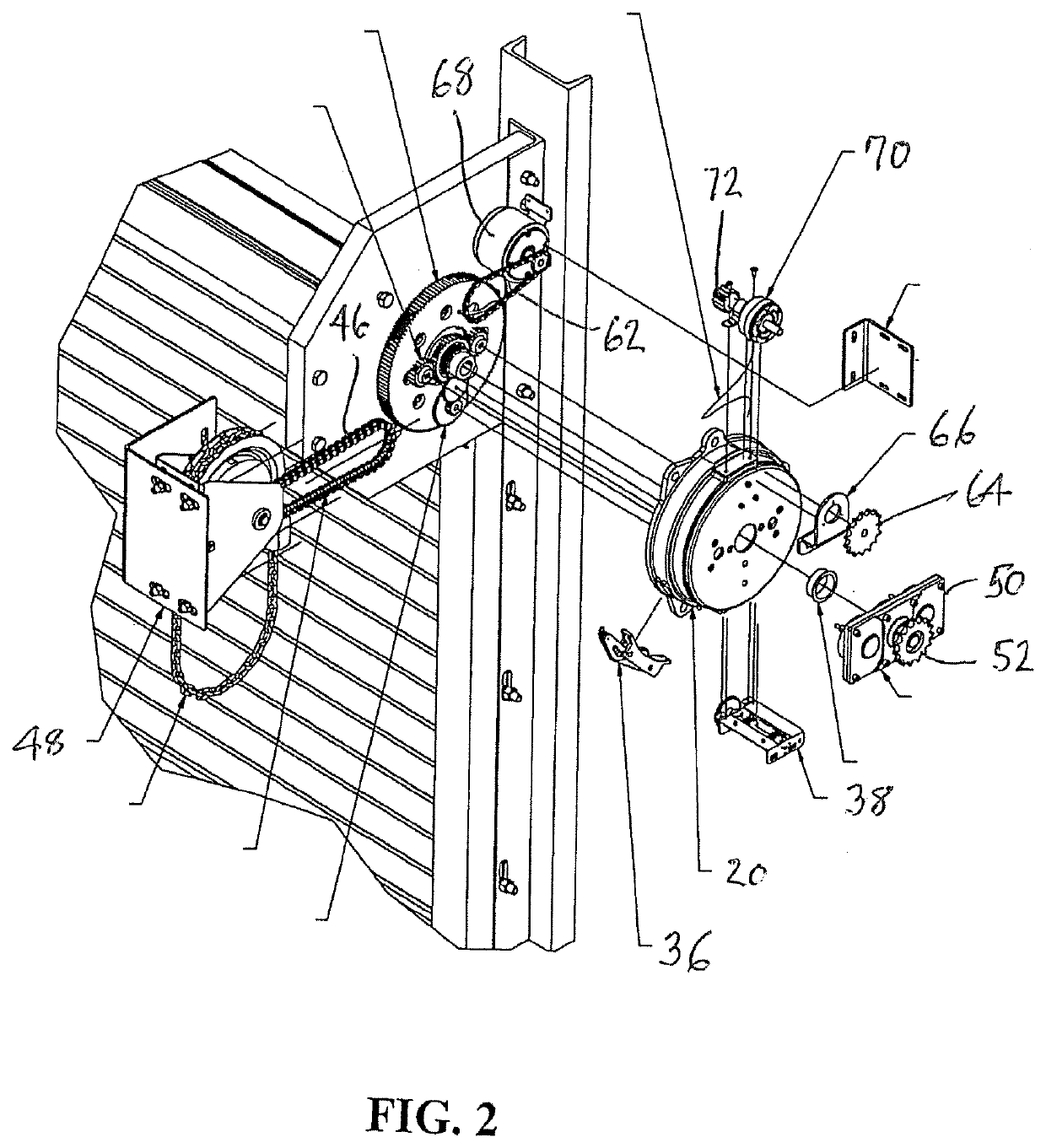
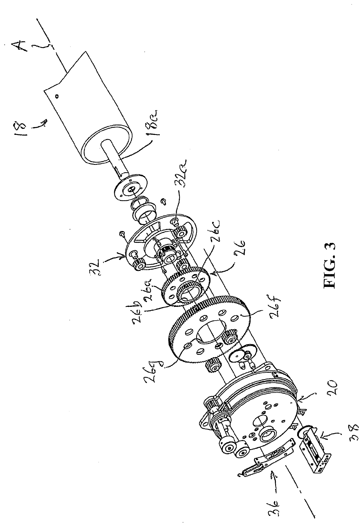
[0035]The operator 10 is mounted on a side drive bracket plate 12 secured to a vertical channel or wall angles 14. A rolling door 16 shown in FIG. 2 is typically mounted on a barrel assembly 18 shown in FIG. 3 that defines an axis A and is operated by the controller 10. The fire door operator 10 is used to control a rolling door that can be raised when rolled onto the barrel assembly 18 when the shaft 18a rotates in a first direction and lowered when the shaft rotates in an opposing direction, as is known in the art. The shaft 18a can be any one of a number of different diameters depending on the size and the weight of the rolling door.

[0036]The operator 10 includes a generally cup-shaped housing 20 has interior space 20a...


PUM


Abstract

A power transfer device for a fire door operator having a pair of drive gears includes a bridge gear box having a drive shaft suitable for being coupled to an external drive. An idle spur gear is fixed to the drive shaft. A pair of spur gears are coupled to the idle spur gear to rotate in response to rotations of the idle spur gear. Spur gear shafts are coupled to the spur gears and arranged to be coupled to the drive gears of the operator so that rotation of the drive shaft by an external drive is translated to simultaneous rotations of the drive gears of the operator.

Description

CROSS-REFERENCE TO RELATED APPLICATION[0001]This application is a Continuation of U.S. patent application Ser. No. 16 / 741,073 filed on Jan. 13, 2020 which is incorporated as if fully set forth herein.BACKGROUND OF THE INVENTION1. Field of the Invention[0002]The present invention generally relates to rolling doors and, more specifically, a power transfer device for a rolling door operator.2. Description of the Prior Art[0003]Roller shutter doors have been known for some time and are used in a variety of applications. They include such categories as: rolling grille; storm doors; fire and smoke doors; air-leakage doors, counter shutters; and, the like. What they have in common is a construction that allows them to be rolled up onto a drum or tube when in the open position; or, to be unreeled from the drum when the door is being lowered. Theses doors are typically used in commercial establishments to seal or close off large doorways, or bays, and can be operated electrically, manually, ...

Claims


Application Information

Patent Timeline
IPC IPC(8): E05B65/10E05F15/668F16H1/28
CPCE05B65/1026E05F15/668E05B2017/043E05B65/104F16H1/28E05F15/684E05Y2201/72E06B9/68E06B9/70E06B9/74E06B9/88E06B2009/689F16H1/206E05Y2400/3013E05Y2900/134
Inventor MAGRO, SEBASTIAN
Owner ALPINE OVERHEAD DOORS INC
Learn More