Bell for a bicycle

a technology for bicycles and bells, applied in the field of bells for bicycles, can solve the problems of reducing or eliminating both bicycles, the position and operation of bells are far from optimal, and the item is not commonly well integrated with the bicycle, so as to achieve the effect of improving safety

Inactive Publication Date: 2015-02-19
BUXTON STEFAN CHRISTOPHER
View PDF19 Cites 1 Cited by
  • Summary
  • Abstract
  • Description
  • Claims
  • Application Information

AI Technical Summary

Benefits of technology

The present invention aims to enhance safety by improving bell design and placement. The hammer element is attached to the bicycle handlebars in a way that allows the cyclist to easily access it with their thumb. The adjustable installation freedom of the bell allows for convenient access while maintaining the bicycle's gear and bramechanisms free to move. In future versions, the hammer may also be accessed above the handlebars.

Problems solved by technology

This movement reduces or eliminates both the cyclist's ability to apply pressure to the brake lever to slow the bicycle down, and their ability to maintain control of the bicycle with only a single hand gripping the handlebar grip.
Particularly, it is noteworthy that under UK law new bicycles must be sold with a bell, but this item is not commonly well integrated with the bicycle.
It is typical for a bell to be included as an afterthought and, therefore, the position and operation of the bell is far from optimal.
This design utilises a ball joint to give flexibility for positioning the mirror on a handlebar, but the bell trigger is not conveniently accessible.

Method used


Image

  • Bell for a bicycle
  • Bell for a bicycle
  • Bell for a bicycle

Examples


Embodiment Construction

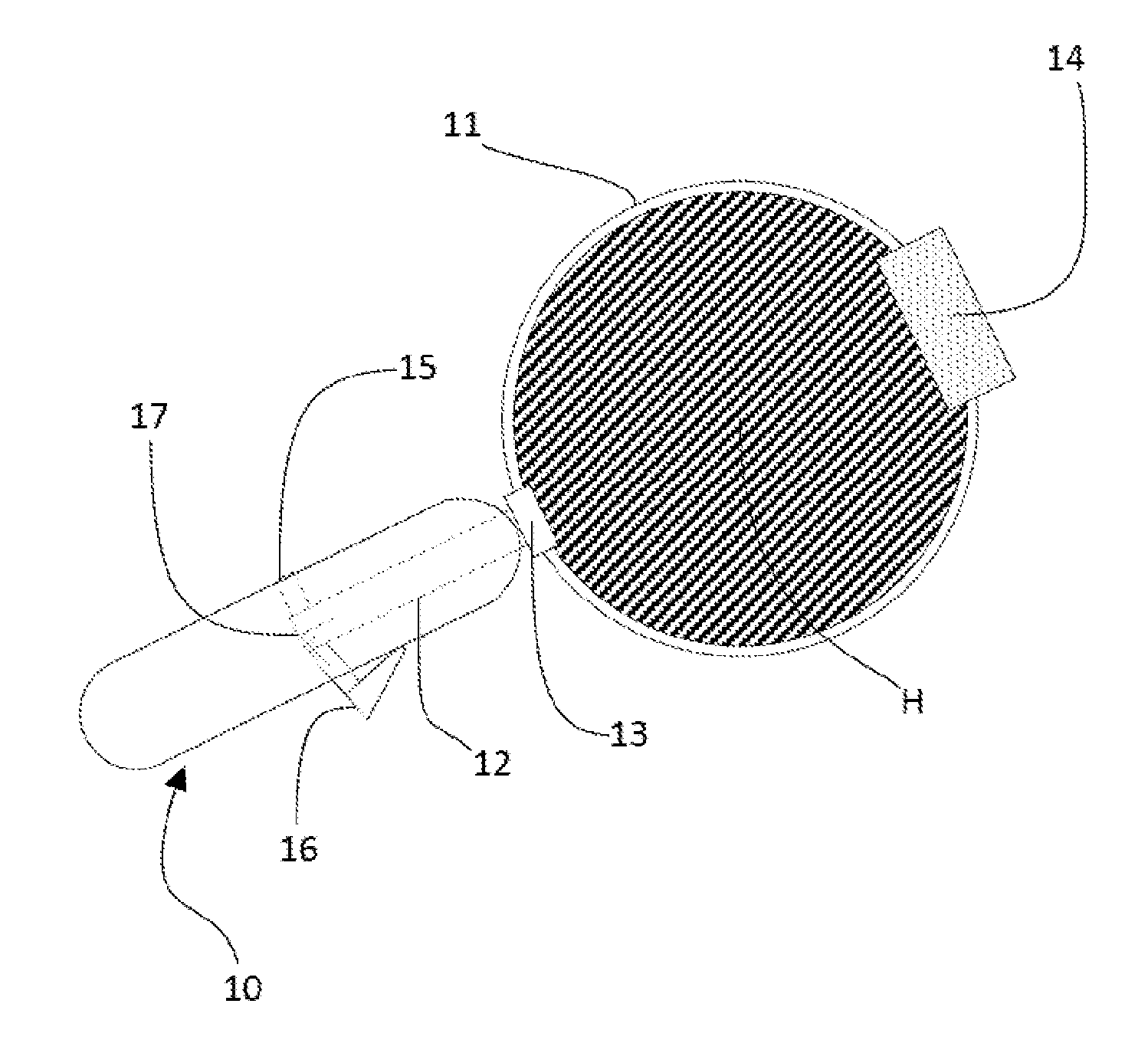
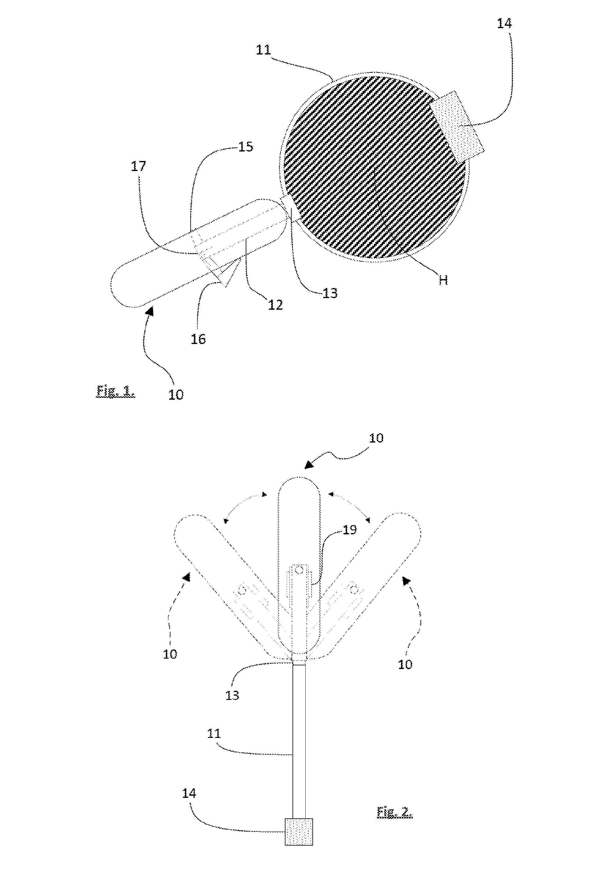
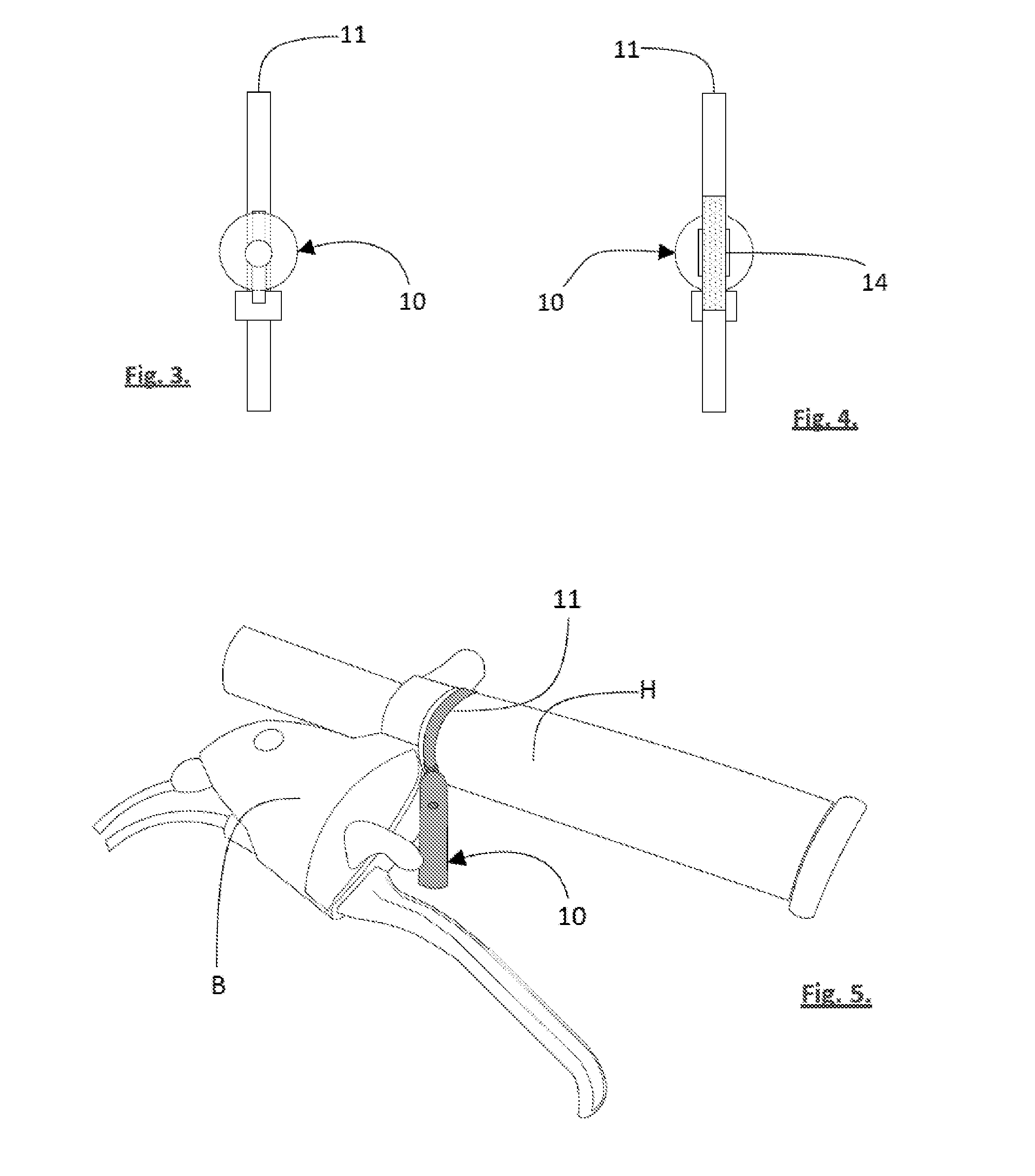
[0037]FIGS. 1 to 5 best illustrate the general components of a bell for a bicycle according to the invention, namely an elongate bell casing / housing 10 arranged to extend from a handlebar mounting means which, in the illustrated form, includes a fixing band 11. The bell includes a bell mounting body portion, in this case a bell arm 12 which is attached at a pivot point 13 to the fixing band 11, enabling the bell arm 12 and its surrounding housing 10 to be adjusted for yaw movement (see ghost outlines of housing 10 in the plan view FIG. 2).

[0038]In the illustrated form it is intended that, as the fixing band 11 is tightened onto a handlebar, the pivot 13 will become fixed (i.e. by withdrawing into a tube part or the like).

[0039]A mechanism for tightening the fixing band 11 is denoted by box 14 and is likely to be a screw operated ratchet or equivalent means. The fixing band 11 itself allows adjustable movement of the bell housing in the pitch direction around a handlebar H such that,...


PUM

PropertyMeasurementUnit
Angleaaaaaaaaaa
Circumferenceaaaaaaaaaa
Resilienceaaaaaaaaaa

Abstract

A bell for a bicycle including a body portion (12) with a stem (23) for supporting a bell casing (10). The body portion / bell casing is able to be adjusted to at an angle from the handlebars H of a bicycle such that a cyclist can more conveniently access hammer element (16) with a thumb from underneath without the bell housing hindering the free movement of the gear and / or brake mechanism.

Description

TECHNICAL FIELD[0001]The present invention relates to a bell for a bicycle as is commonly used as a warning signal to pedestrians or other road users.BACKGROUND ART[0002]A conventional bicycle warning bell (or simply hereinafter referred to as a “bell”) is usually mounted onto bicycle handlebars between the brake (and / or gear) mechanism and the handlebar stem. The space between the brake mechanism and the distal end of the handlebar is reserved for a rubber hand grip (hereinafter referred to as a “handlebar grip”) and optional bar end.[0003]In normal use, the hands of a cyclist grip the handlebar grip with fingers being used to actuate the brake (and also gear mechanism in certain types of “lever” or “rapid fire” gear shifters) with a thumb gripping the underside of the handlebar grip where it is also able to actuate the opposing gear mechanism. Variations of this normal use are based on the type of gear mechanism.[0004]In order to actuate a bell when it is in its conventional posit...

Claims


Application Information

Patent Timeline
IPC IPC(8): G10K1/26
CPCG10K1/26B62J3/04Y10T29/49826
Inventor BUXTON, STEFAN CHRISTOPHER
Owner BUXTON STEFAN CHRISTOPHER
Why Eureka
Try Eureka