Staple gun automatically applicable to staples of multiple sorts

a technology of multiple kinds and staple guns, applied in the field of staple guns, can solve the problems of two aforesaid glitches and achieve the effect of convenient us

Active Publication Date: 2015-02-19
SAME YONG INDAL
View PDF12 Cites 11 Cited by
  • Summary
  • Abstract
  • Description
  • Claims
  • Application Information

AI Technical Summary

Benefits of technology

[0007]In view of the aforesaid drawbacks of the prior art, it is an objective of the present invention to provide a staple gun which is automatically applicable to staples of multiple specifications and thicknesses without being tuned by a user and thus manifests ease of use.
[0008]Another objective of the present invention is to provide a staple gun which is applicable to staples of multiple specifications and variable thickness and thus has wide application.
[0009]In order to achieve the above and other objectives, the present invention provides a staple gun automatically applicable to staples of multiple sorts, comprising: a casing having a front blocking surface; a magazine disposed in the casing and adapted to hold a plurality of staples; and a staple delivery element and a resilient element disposed at the magazine. The magazine comprises at least a staple cutting portion. The staple cutting portion has a top surface, a front end surface, and a guiding surface connected between the top surface and the front end surface. The front end surface and the guiding surface of the staple cutting portion face the front blocking surface of the casing. A clearance for passing the staples is disposed between the front end surface of the staple cutting portion and the front blocking surface of the casing. The staple delivery element pushes the staples in the magazine in a staple delivering direction, such that one of the staples abuts against the front blocking surface of the casing. The resilient element enables the staples to push the front end surface and the guiding surface of the staple cutting portion of the magazine, such that the magazine moves relative to the casing in a clearance adjustment direction opposite to the staple delivering direction.
[0010]As regards the staple gun of the present invention, the breadth of the clearance is designed to allow staples of the least thickness (in comparison with the thicknesses of staples in wide use) to squeeze through the clearance. The staple gun of the present invention is also applicable to staples which have large thicknesses and a head portion (such as T-shaped staples, U-shaped staples, and n-shaped staples) because, as soon as the foremost staple is struck, not only does the head portion of the staple slide across the guiding surface of the staple cutting portion of the magazine to reach the front end surface, but the staple cutting portion also advances in the clearance adjustment direction, such that the breadth of the clearance is automatically adjusted in accordance with the thickness of the staple to thereby allow the staple to squeeze through the clearance. Hence, the staple gun of the present invention is automatically applicable to staples of multiple thicknesses without being tuned by a user. Furthermore, the staple gun of the present invention will work, provided that the thickness of the staples is less than the least distance between the top surface of the staple cutting portion and the front blocking surface of the casing. Accordingly, the staple gun of the present invention has wide application.

Problems solved by technology

However, after loading a conventional staple gun with staples, a user often forgets to tune the controlling element, thereby ending up with the two aforesaid glitches.

Method used


Image

  • Staple gun automatically applicable to staples of multiple sorts
  • Staple gun automatically applicable to staples of multiple sorts
  • Staple gun automatically applicable to staples of multiple sorts

Examples


Embodiment Construction

[0030]In the embodiments below and the accompanying drawings, identical or similar components and structural features thereof are denoted with identical reference numerals.

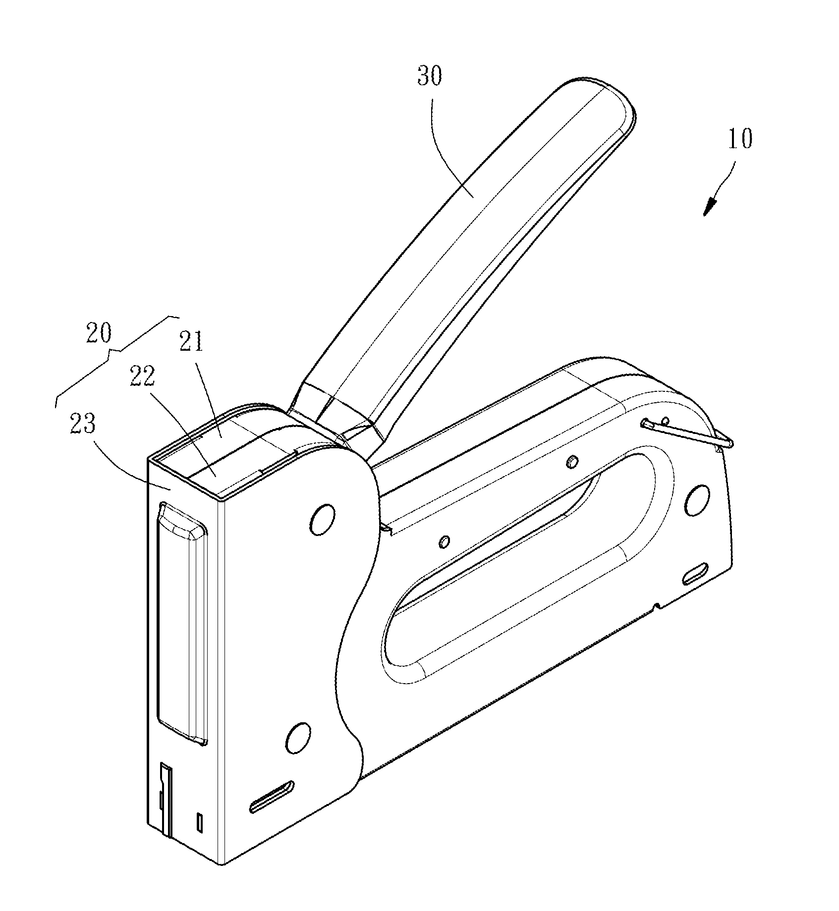
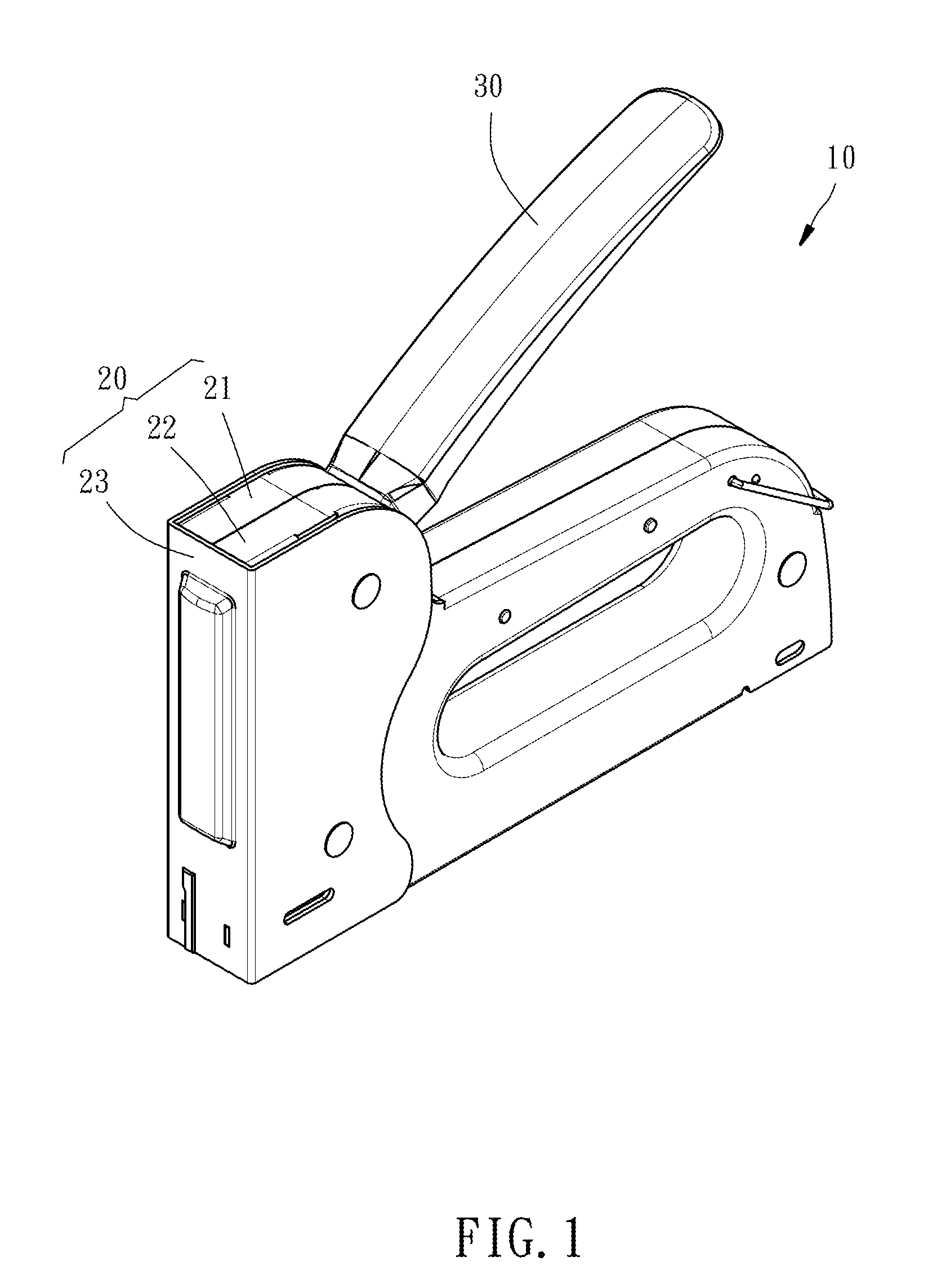
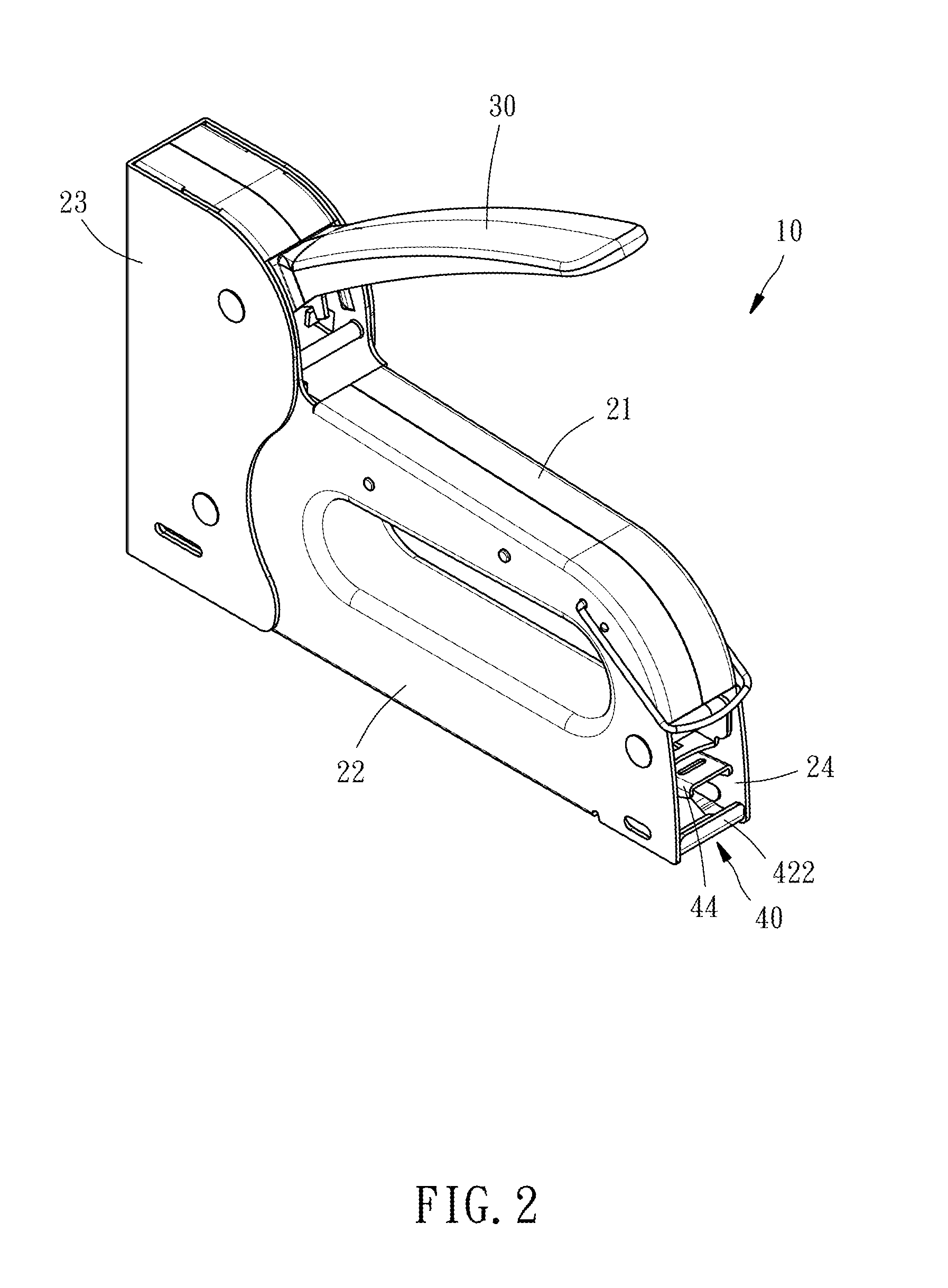
[0031]Referring to FIG. 1 and FIG. 2, when viewed from the outside, a staple gun 10 automatically applicable to staples of multiple sorts according to a first preferred embodiment of the present invention comprises a casing 20 and an arm 30 extending outward from the casing 20. The casing 20 has therein a magazine 40, a staple delivery element 50, and a resilient element 60 as shown in FIG. 3 through FIG. 7, and a staple striking element 70 (shown in FIG. 8) driven by the arm 30 to strike and eject staples in a staple striking direction D1. The arm 30, the staple striking element 70, and their operation are well known to persons skilled in the art and thus are not describe herein for the sake of brevity.

[0032]Referring to FIG. 1 and FIG. 2, the casing 20 comprises a left case element 21, a right case element 22, a...


PUM


Abstract

A staple gun includes: a casing having a front blocking surface; a magazine disposed in the casing; and a staple delivery element and a resilient element disposed at the magazine. The magazine includes at least a staple cutting portion each having a top surface, a front end surface, and a guiding surface connected between the top surface and the front end surface. The front end surface and the guiding surface face the front blocking surface. A clearance for passing staples is disposed between the front end surface and the front blocking surface. The staple delivery element pushes staples in the magazine in a staple delivering direction. The resilient element enables staples to push the front end surface and the guiding surface of the staple cutting portion of the magazine, such that the magazine moves relative to the casing in a clearance adjustment direction opposite to the staple delivering direction.

Description

BACKGROUND OF THE INVENTION[0001]1. Technical Field[0002]The present invention relates to staple guns, and more particularly, to a staple gun automatically applicable to staples of multiple sorts.[0003]2. Description of Related Art[0004]Plenty of conventional staple guns applicable to staples of different shapes are commercially available. Each of them essentially comprises a magazine, a staple delivery element, a staple striking element, and an arm. The magazine holds T-shaped staples, linearly-shaped staples, U-shaped staples, n-shaped staples, and the like. The staple delivery element delivers the staples to a ready-to-eject position below the staple striking element. A users uses the arm to drive the staple striking element to strike the staple at the ready-to-eject position such that the staple is ejected downward.[0005]To switch to staples of a different thickness, the user has to tune a controlling element of a conventional staple gun in order to eject the staples one by one ...

Claims


Application Information

Patent Timeline
Patent Type & Authority Applications(United States)
IPC IPC(8): B25C5/16
CPCB25C5/1651B25C5/1606B25C5/1658B25C5/06B25C5/11
Inventor CHEN, KUAN-CHIHTU, CHENG-LUNG
Owner SAME YONG INDAL
Why Eureka
Try Eureka