Walker Device with Air Tank Holder

a technology of air tank and walker, which is applied in the field of can solve the problems of affecting the user's gait, limiting mobility, and not disclosing the foldable walker with air tank holder that does not detract from the user's mobility,

Inactive Publication Date: 2015-02-19
FREEMAN JOHN
View PDF8 Cites 10 Cited by
  • Summary
  • Abstract
  • Description
  • Claims
  • Application Information

AI Technical Summary

Benefits of technology

[0018]Another object of the present invention is to provide a walker device with an air tank holder wherein the air tank holder comprises a vertical support, an upper ring, and a lower ring with a means to prevent an air tank from falling therethrough.
[0019]Yet another object of the present invention is to provide a new and improved walker device with an air tank holder wherein the air tank holder protrudes outward and away from the user to allow the user to use the walker device in a conventional manner without hitting the air tank holder.

Problems solved by technology

These devices, however, do not disclose a foldable walker with an air tank holder that does not detract from the user's mobility.
Such positioning of the carrier gives less room for the user to position himself or herself between the walker device and can interfere with the user's gait when walking, which is particularly problematic for users with limited mobility.
While the device of Olson discloses a foldable walker with a built in carrier for an air tank, the device of Olson fails to disclose a vertical support with an upper and a lower ring for holding an air tank.
Additionally, the placement of the carriers in the second embodiment of the Carroll device obstructs the view of the user when using the walker.
These devices are limited in the fact that the air tank holders protrude inward and toward the user, thereby reducing the amount of room within the walker.

Method used


Image

  • Walker Device with Air Tank Holder
  • Walker Device with Air Tank Holder
  • Walker Device with Air Tank Holder

Examples


Embodiment Construction

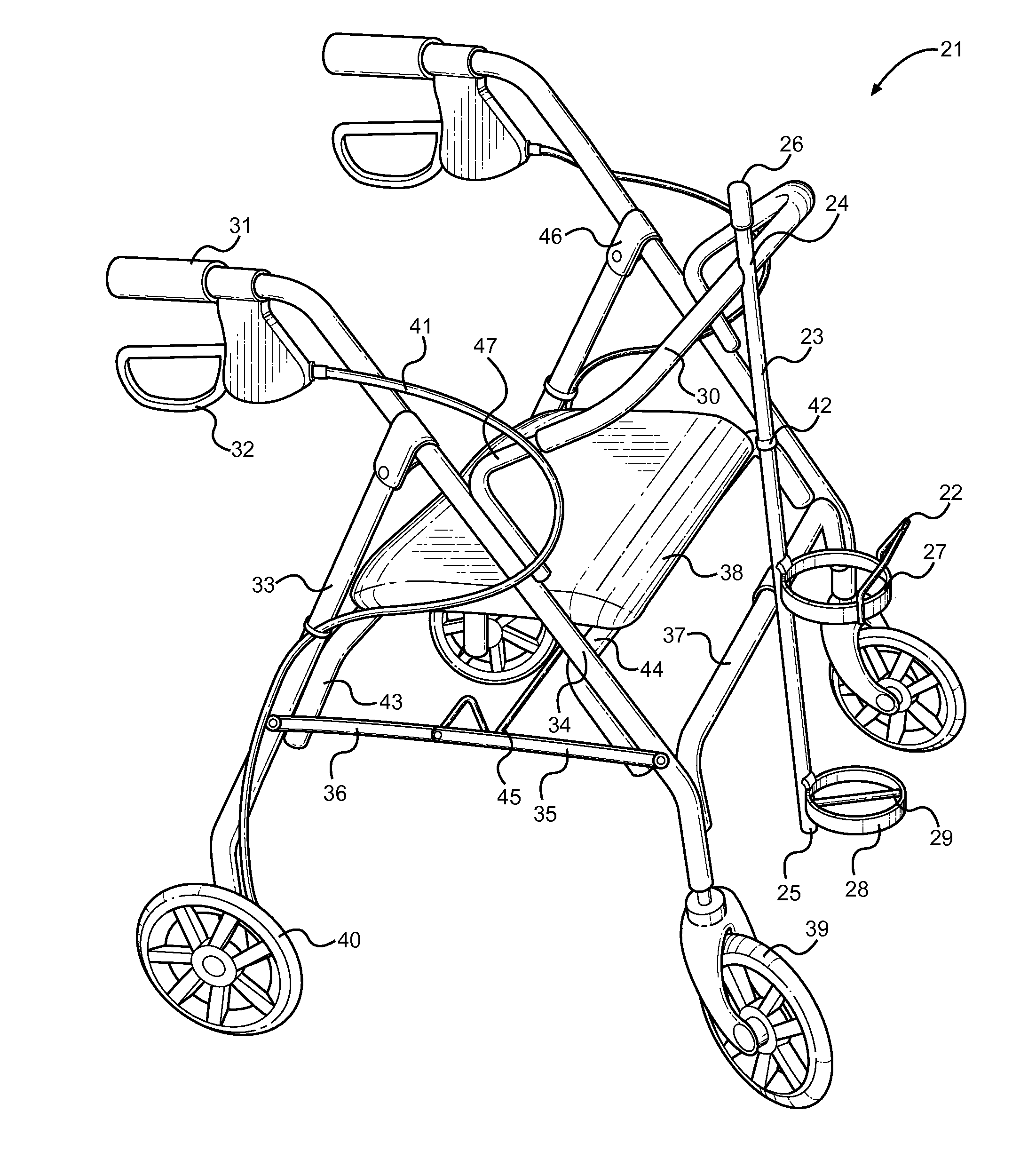
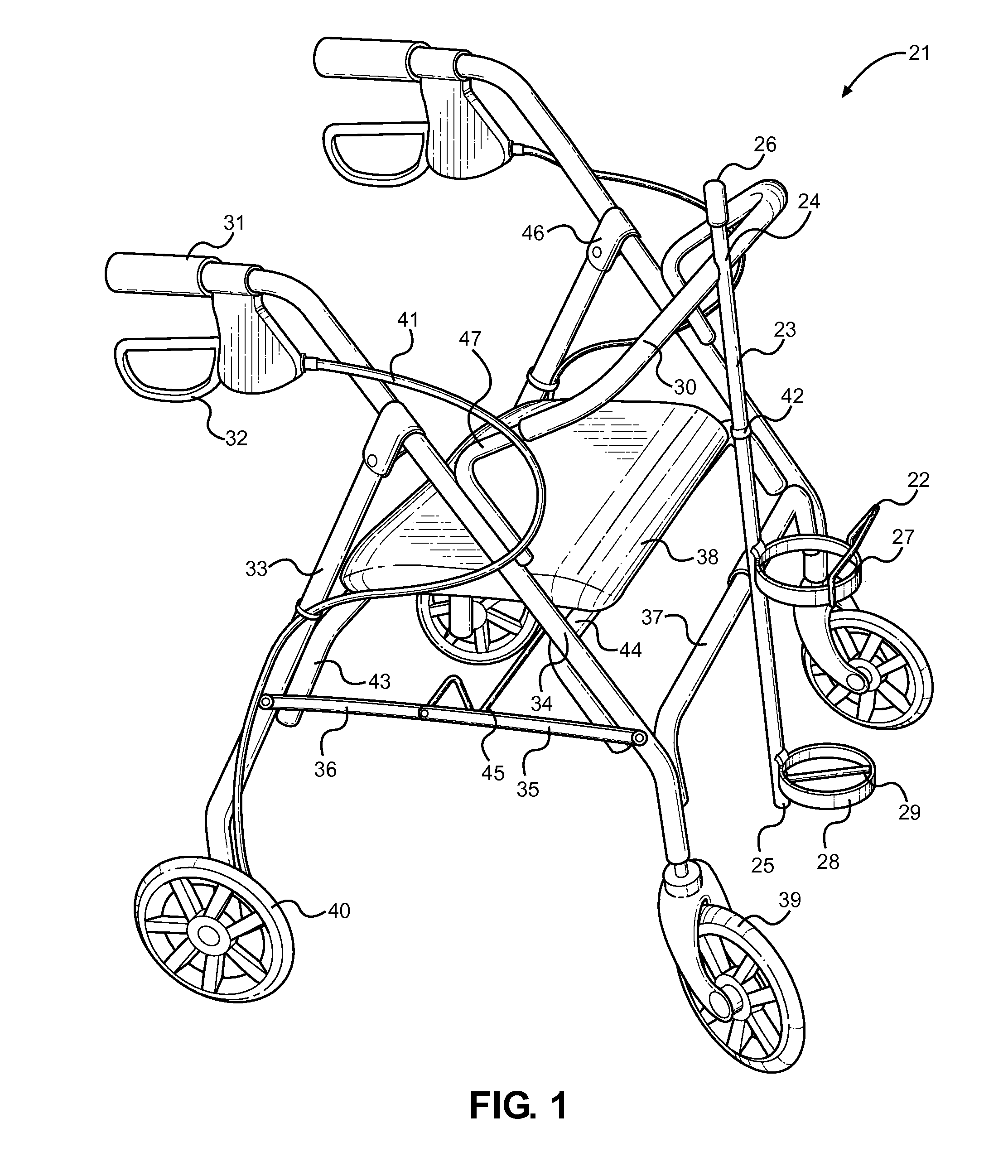
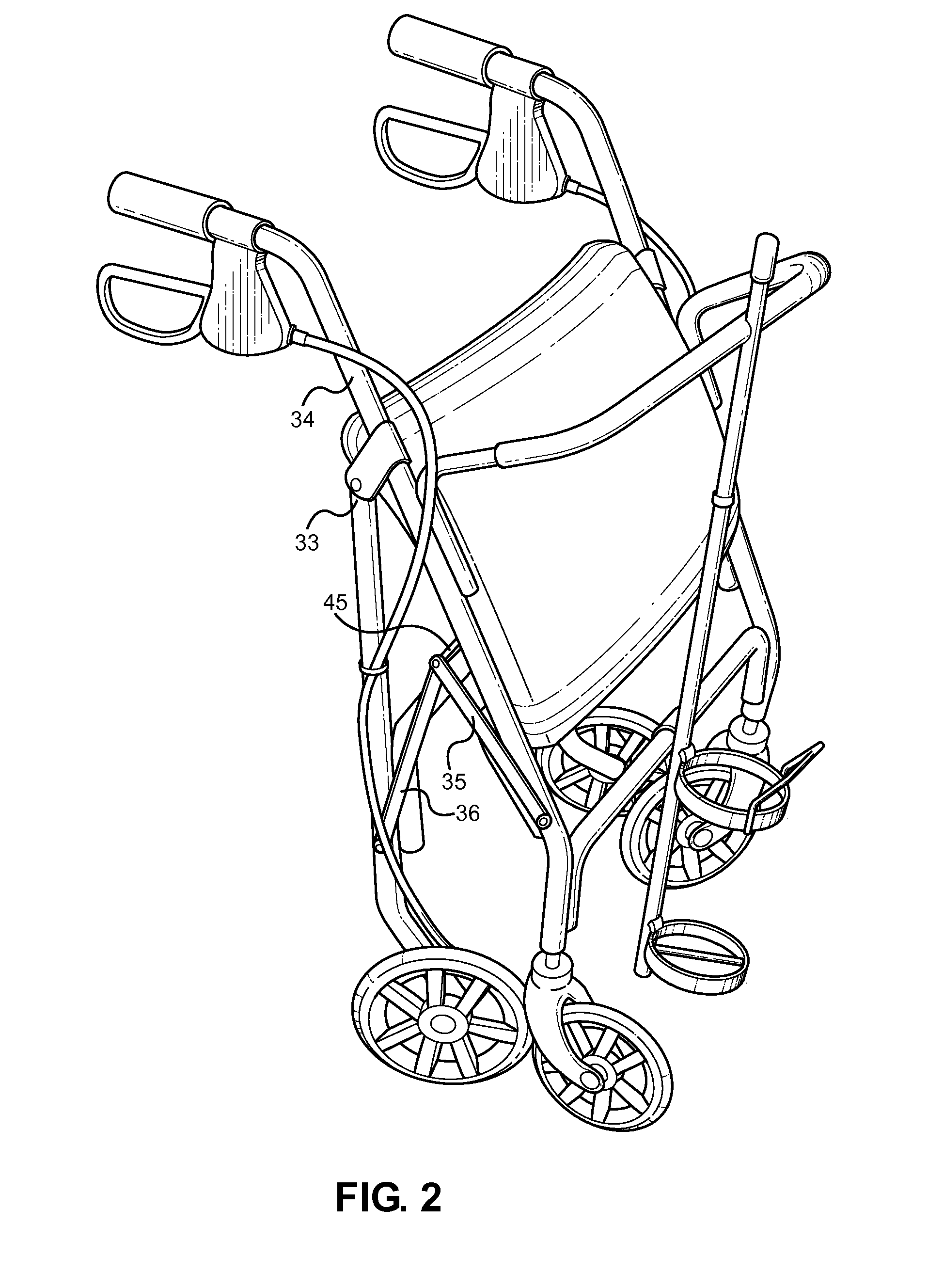
[0026]References are made herein to the attached drawings. Like reference numerals are used throughout the drawings to depict like or similar elements of the walker device with an air tank holder. For the purposes of presenting a brief and clear description of the present invention, the preferred embodiment will be discussed as used to conveniently transport an air tank when using a walker. The figures are intended for representative purposes only and should not be considered to be limiting in any respect.

[0027]Referring now to FIG. 1, there is shown a perspective view of the present invention. The present invention comprises a walker 21 having a pair of side frames that are connected via a set of horizontal bars, front and rear wheels with a braking mechanism, an oxygen tank holder, and a pivotally attached seat. In the illustrated embodiment, the side frames comprise an inverted Y-shape. However, the side frames may be of various shapes and constructions in accordance with the pre...


PUM


Abstract

Disclosed is a foldable walker device with an air tank holder. The purpose of the present invention is to enable individuals to easily transport an air tank while using a walker. The air tank holder includes a vertical support with upper and lower outwardly protruding rings that are used to hold an air tank in place. The upper ring is positioned at a substantial midpoint of the vertical support to maintain the air tank in an upright position. The lower ring can be positioned at the bottom of the vertical support and can have a rod extending along the diameter of the ring to support the base of the air tank. The air tank holder is affixed to a front of a walker to prevent the air tank holder from hitting the user's legs when the user is walking.

Description

CROSS REFERENCE TO RELATED APPLICATION[0001]This application claims the benefit of U.S. Provisional Application No. 61 / 866,800 filed on Aug. 16, 2013. The above identified patent application is herein incorporated by reference in its entirety to provide continuity of disclosure.BACKGROUND OF THE INVENTION[0002]1. Field of the Invention[0003]The present invention relates to a walker with an air tank holder. More specifically, the present invention pertains to an improved foldable walker with an air tank holder affixed centrally at the front portion thereof. The air tank holder protrudes outwardly and faces away from the user so as to allow the user to walk without added hindrance.[0004]A walker is a tool for disabled or elderly people who need additional support to maintain balance or stability while walking. When using a walker, the user walks with the walker surrounding his or her front and sides so that the user can place his or her hands on the sides of the walker where the handl...

Claims


Application Information

Patent Timeline
Patent Type & Authority Applications(United States)
IPC IPC(8): A61H3/04
CPCA61H3/04A61H2003/046A61H2201/1633A61H2201/0161A61H2003/002
Inventor FREEMAN, JOHN
Owner FREEMAN JOHN
Why Eureka
Try Eureka