
Eureka
For R&D, Eureka makes reading and utilizing patents & technical documents easy.
Eureka AIR
Designed for self-driven R&D workflows. Generate viable solutions, solve complex R&D challenges, empower your innovation with AI.

Eureka Materials
Designed for material experts only. Revolutionize your material R&D, from search, analyze, to developing new materials.

TechResearch
Generate reliable direction feasibility study reports for your R&D in just a few steps.

TechSeek
Discover and master advanced knowledge NOW. Basics, ideas, possibilities, all at once.

TechMind
As an expert in R&D Theories, TechMind can generates customized viable solutions instantly.

TechRisk
Analyze your overall solution with one click, know your potential R&D risks in advance.

TechMonitor
Get weekly tech updates, stay abreast of the latest tech innovations and key insights.
Structure for mounting a clip for a writing implement
- Summary
- Abstract
- Description
- Claims
- Application Information
AI Technical Summary
Problems solved by technology
Method used
Image

Examples
Example
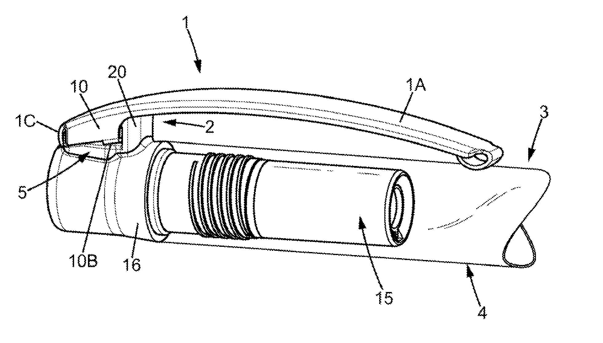
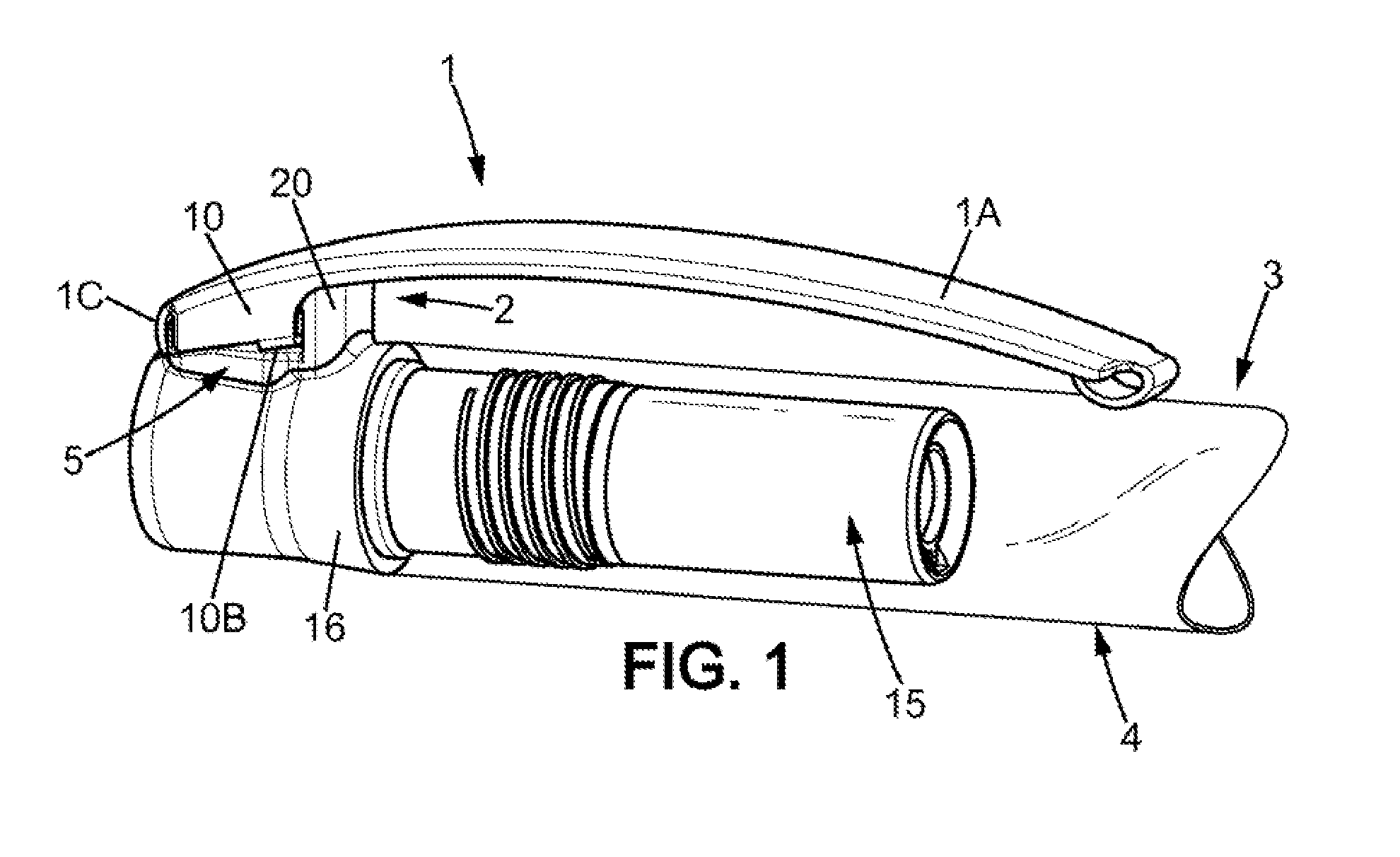
[0034]According to a first embodiment of a mounting structure according to the embodiments of the present invention, the mounting structure shown in FIG. 1 comprises a receiving member 2 integrally formed with a generally tubular member 15. The generally tubular member 15 is adapted for mounting at the rear of a barrel 4 of a writing implement 3, as is also represented in FIG. 1. The generally tubular member comprises a generally cylindrical rear portion 16 positioned at the rear of the barrel 4 as an extension of the latter once the member 15 is mounted on the barrel. The receiving member 2 radially projects from the rear portion 16.
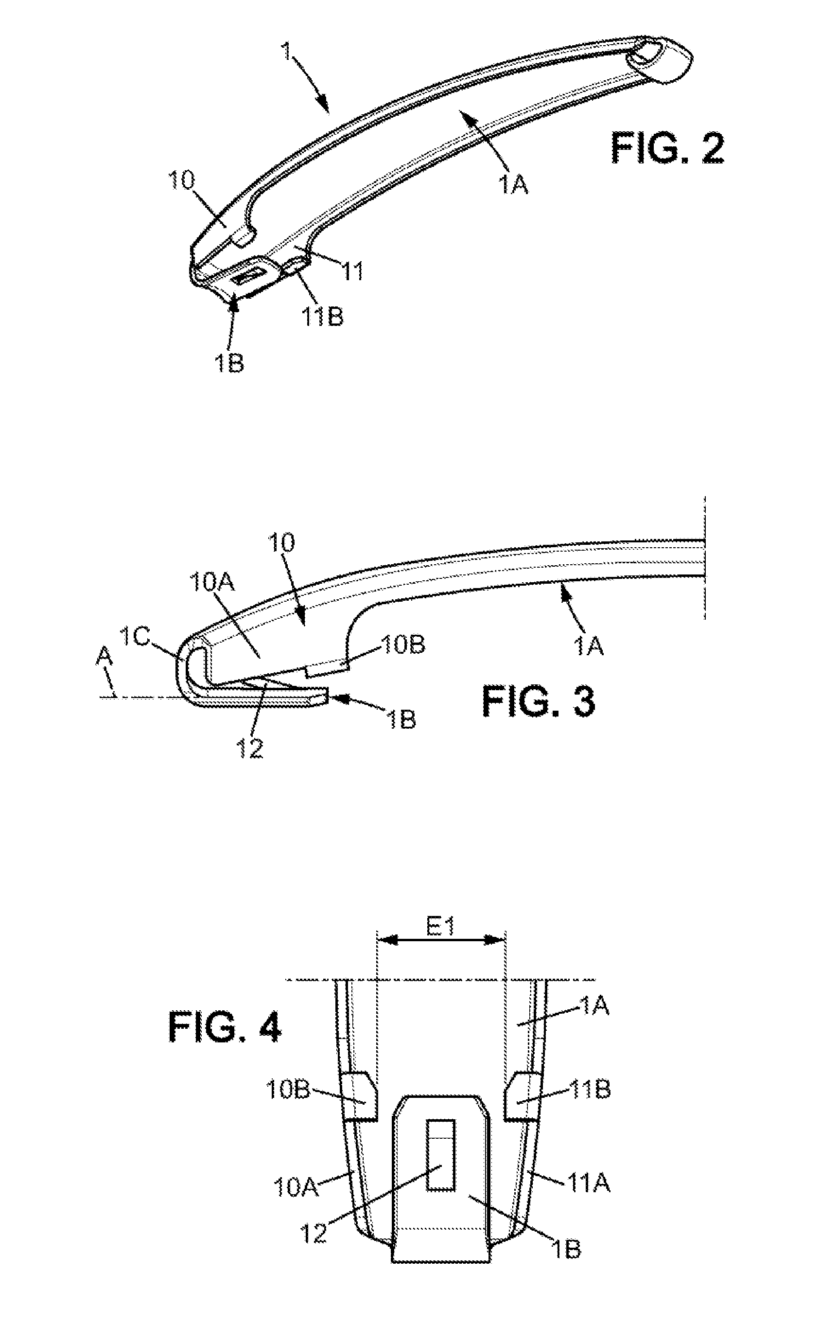
[0035]The clip 1 comprises a main body 1A and a resiliently deformable curved portion 1C connecting the main body 1A to a coupling portion inserted into a base 5 of the receiving member.
[0036]The receiving member 2 comprises an abutment member 20 having at least one pivot stop adapted to cooperate with a pivot-limiting hook 10B provided on a sidewall 10...
Example
[0054]In a second embodiment of a mounting structure according to the embodiments of the present invention, not represented in the figures, it is possible to eliminate the reinforcing front wall 30 and to provide on the abutment member 20 a protruding upper part similar to the abutment 30C described above. It is also possible to eliminate a portion of the central longitudinal wall 40 above the catch opening 8, meaning the transverse reinforcing portion 6 and the abutment member 20 are no longer interconnected by this wall. These arrangements taken together or separately save a small amount of plastic, but may still have the disadvantage of weakening the receiving member 2.
[0055]It is understood that a structure for mounting a clip for a writing implement is not necessarily intended to be placed at the rear of the writing implement, and may for example be fitted on a protective cap for a tip at the front of the writing implement.
[0056]The invention also relates to an assembly of plas...
PUM
 Abstract
Description
Claims
Application Information
 - R&D Engineer
- R&D Manager
- IP Professional
- Industry Leading Data Capabilities
- Powerful AI technology
- Patent DNA Extraction
Browse by: Latest US Patents, China's latest patents, Technical Efficacy Thesaurus, Application Domain, Technology Topic, Popular Technical Reports.
© 2024 PatSnap. All rights reserved.Legal|Privacy policy|Modern Slavery Act Transparency Statement|Sitemap|About US| Contact US: help@patsnap.com