Wire grid polarization film, method for manufacturing wire grid polarization film, liquid crystal display using wire grid polarization film, and method for manufacturing mold for forming wire grids thereof

a technology of polarization film and wire grid, which is applied in the direction of polarizing elements, instruments, natural mineral layered products, etc., can solve the problems of heavy weight and large thickness of conventional wire grid polarization film, and achieve the effect of low cos

Inactive Publication Date: 2006-07-20
LG ELECTRONICS INC
View PDF0 Cites 45 Cited by
  • Summary
  • Abstract
  • Description
  • Claims
  • Application Information

AI Technical Summary

Benefits of technology

[0013] The present invention has been made to solve the above problems, and it is an object of the present invention to provide a method for manufacturing wire grid polarizers of a large area in mass production at low costs, and a mold for the wire grid polarization film for mass production.

Problems solved by technology

With this structure, a substantial portion of light emitted from the light source is lost while passing through the BLU.
This means that the LCD has a low utilization efficiency of light.
However, since the DBEF is manufactured to form a multilayer film by crossing an optically anisotropic polymer film and an optically isotropic polymer film, it is expensive, and made via a complicated manufacturing process.
However, since a shorter period of the metal grid complicates a process of manufacturing the wire grid polarizer, the wire grid polarization film has been used mainly in the range of microwaves or infrared radiation.
Thus, the conventional wire grid polarization film has a restriction in an increase in area thereof so as to be available for a medium or large sized display of 10 inches or more, and is very expensive.
In addition, due to use of the glass substrate, the conventional wire grid polarization film has problems of heavy weight and large thickness even if the wire grid polarization film is manufactured to have a large area.

Method used


Image

  • Wire grid polarization film, method for manufacturing wire grid polarization film, liquid crystal display using wire grid polarization film, and method for manufacturing mold for forming wire grids thereof
  • Wire grid polarization film, method for manufacturing wire grid polarization film, liquid crystal display using wire grid polarization film, and method for manufacturing mold for forming wire grids thereof
  • Wire grid polarization film, method for manufacturing wire grid polarization film, liquid crystal display using wire grid polarization film, and method for manufacturing mold for forming wire grids thereof

Examples


Embodiment Construction

[0037] Preferred embodiments of the present invention will be described in detail with reference to the accompanying drawings, in which like components are denoted by the same reference numerals. Well-known functions and constructions which can make the subject matter of the present invention unclear will be omitted hereinafter.

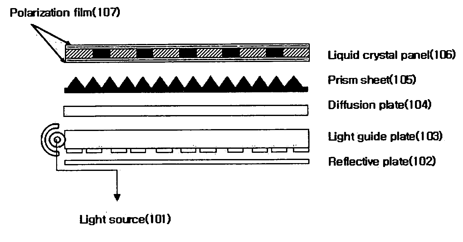
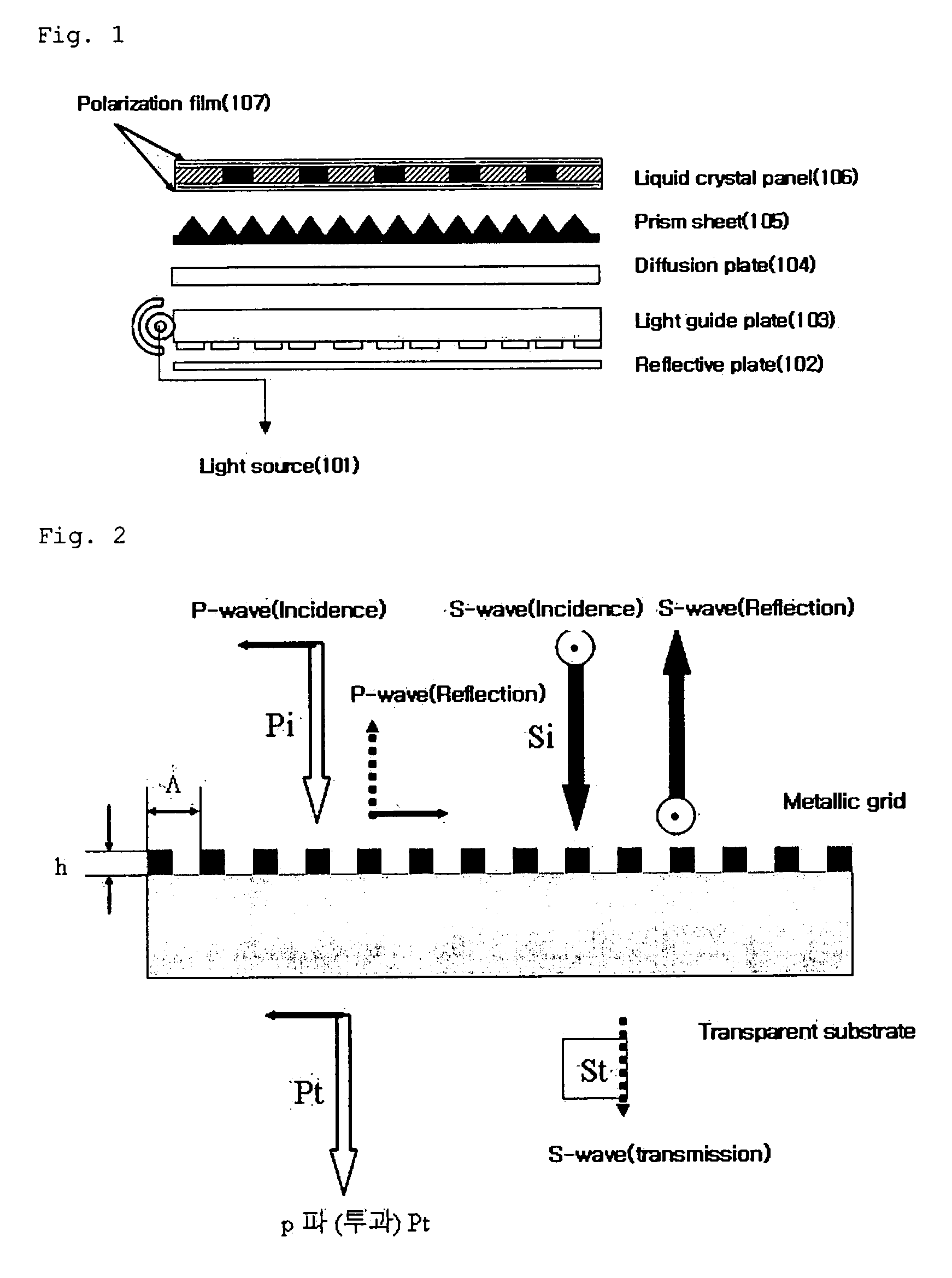
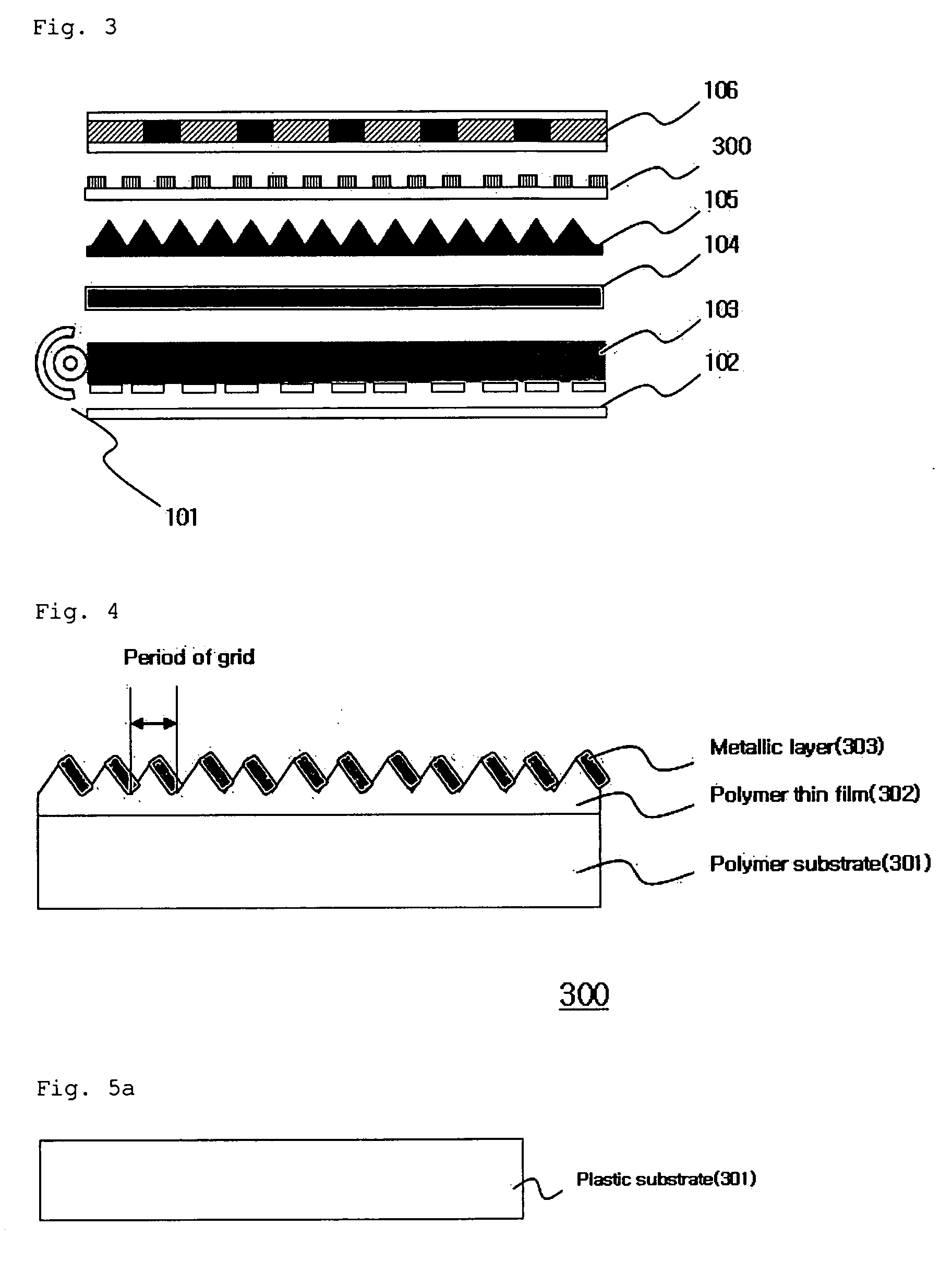
[0038]FIG. 3 shows a stacking sequence of an LCD panel using a wire grid polarization film in accordance with one embodiment of the present invention.

[0039] In this embodiment, the LCD panel comprises a light source 101, a reflective plate 102, a light guide plate 103, a diffusion plate 104, a prism sheet 105, a wire grid polarization film 300, and a liquid crystal panel 106.

[0040]FIG. 3 schematically shows a stacked position of a wire grid polarization film 300 according to this embodiment.

[0041] Referring to FIG. 3, the reflective plate 102 is positioned at the lowermost portion of the LCD panel, and the light guide plate 103, the diffusion plate 104 an...


PUM

PropertyMeasurementUnit
wavelength bandaaaaaaaaaa
metallicaaaaaaaaaa

Abstract

A wire grid polarization film, a method for manufacturing the same, and a method for manufacturing a mold for forming grids thereof are disclosed. The wire grid polarization film comprises a substrate, a grid structure layer stacked on the substrate, and at least one metallic layer formed on one side of the grid structure layer. The method for manufacturing the wire grid polarization film comprises preparing a substrate, applying a grid structure layer to an upper surface the substrate, forming a grid pattern on the grid structure layer, and depositing a metal layer on the grid pattern. The method for manufacturing the mold comprises applying a photoresist film on a substrate, patterning the photoresist film using interference fringes via laser, developing the photoresist film, stacking a material for forming a grid pattern of the wire grid polarization film on the photoresist film, and removing the substrate and the photoresist film.

Description

CROSS-REFERENCE TO RELATED APPLICATIONS [0001] Pursuant to 35 U.S.C. § 119(a), this application claims the benefit of earlier filing date and right of priority to Korean Patent Application No. 10-2005-0005123 filed on Jan. 19, 2005, which is hereby incorporated by reference herein in its entirety. BACKGROUND OF THE INVENTION [0002] 1. Field of the Invention [0003] The present invention relates to a wire grid polarization film, and a method for manufacturing a mold for forming a grid of the same. [0004] 2. Description of the Related Art [0005] Generally, a liquid crystal display (LCD) is a flat panel display which is used in a wide variety of applications including mobile phones, notebook computers, monitors, televisions, etc. The LCD is a device for transmitting or shielding light by changing an arrangement of liquid crystals via application of electric signals to respective pixels in a liquid crystal panel positioned between two polarizing plates. Thus, a separate light source is r...

Claims


Application Information

Patent Timeline
Patent Type & Authority Applications(United States)
IPC IPC(8): D03D15/00B32B15/01B29C33/40B32B19/00G02B5/30
CPCG02B5/3058Y10T442/109Y10T442/126G02B5/30G02F1/1335
Inventor LEE, KI-DONG
Owner LG ELECTRONICS INC
Why Eureka
Try Eureka