Joint structure between members

a joint structure and member technology, applied in the direction of mechanical control devices, instruments, borehole/well accessories, etc., can solve the problems of increasing mold cost and difficult to reduce the production cost of elastic members, and achieve the effect of enhancing the hardness of elastic members, reducing the force of insertion of elastic members into annular frames, and increasing the engagement for

Active Publication Date: 2008-12-30
PIOLAX CO LTD +1
View PDF21 Cites 43 Cited by
  • Summary
  • Abstract
  • Description
  • Claims
  • Application Information

AI Technical Summary

Benefits of technology

[0009]Particularly when the holding part of the elastic member has a spherical shape as in Patent Document 1, the inside diameter of the holding part gradually decreases from the vertical middle position thereof toward the hole, i.e., downward. If the elastic member of Patent Document 1 is molded using a mold that is vertically joined and separated, an undercut will be formed inside of the holding part. Therefore, in order to allow the removal of the molded elastic member from the mold, a slide core must be employed as part of the mold corresponding to the holding part. This increases the mold cost and makes it difficult to reduce the production cost of the elastic member.
[0010]The present invention has been made in view of the foregoing point and therefore its object is to allow the elastic member for joining the first and second members therethrough to be easily molded without any undercut being formed, thereby reducing the production cost of the elastic member.

Problems solved by technology

This increases the mold cost and makes it difficult to reduce the production cost of the elastic member.

Method used


Image

  • Joint structure between members
  • Joint structure between members
  • Joint structure between members

Examples


Embodiment Construction

[0040]A preferred embodiment of the present invention will be described below with reference to the drawings. The following description of the preferred embodiment is illustrative only and is not intended to limit the scope, applications and use of the invention.

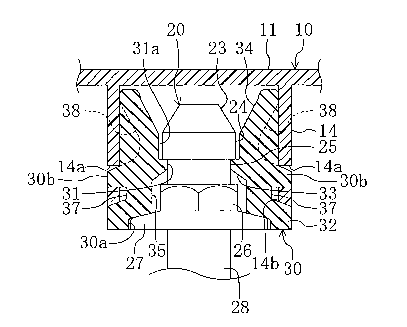
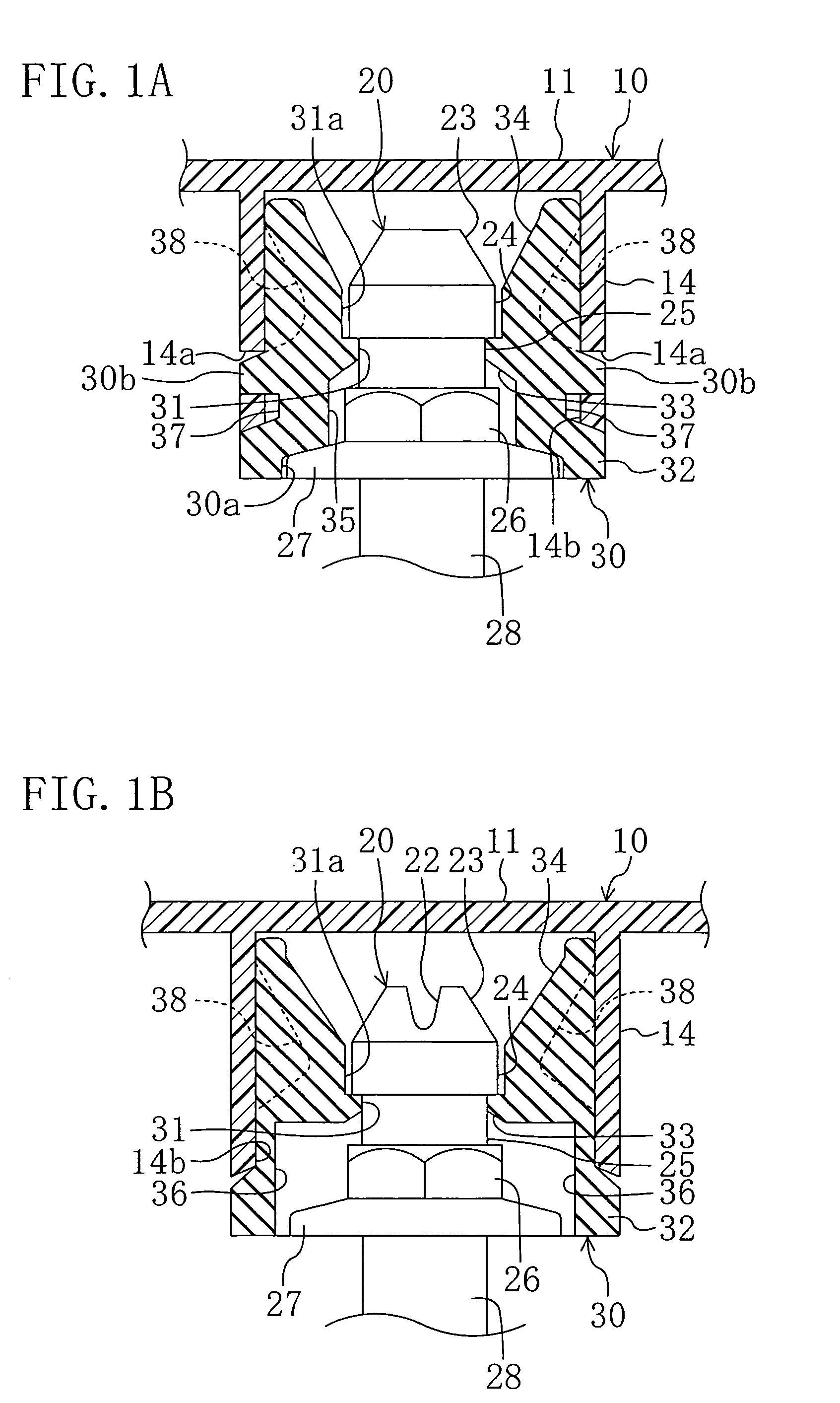
[0041]FIGS. 1A and 1B show the case where a joint structure between members according to an embodiment of the invention is applied in joining an engine cover (first member) 10 for covering a vehicle engine (not shown) from above to an adapter (second member) 20 attached to the engine.

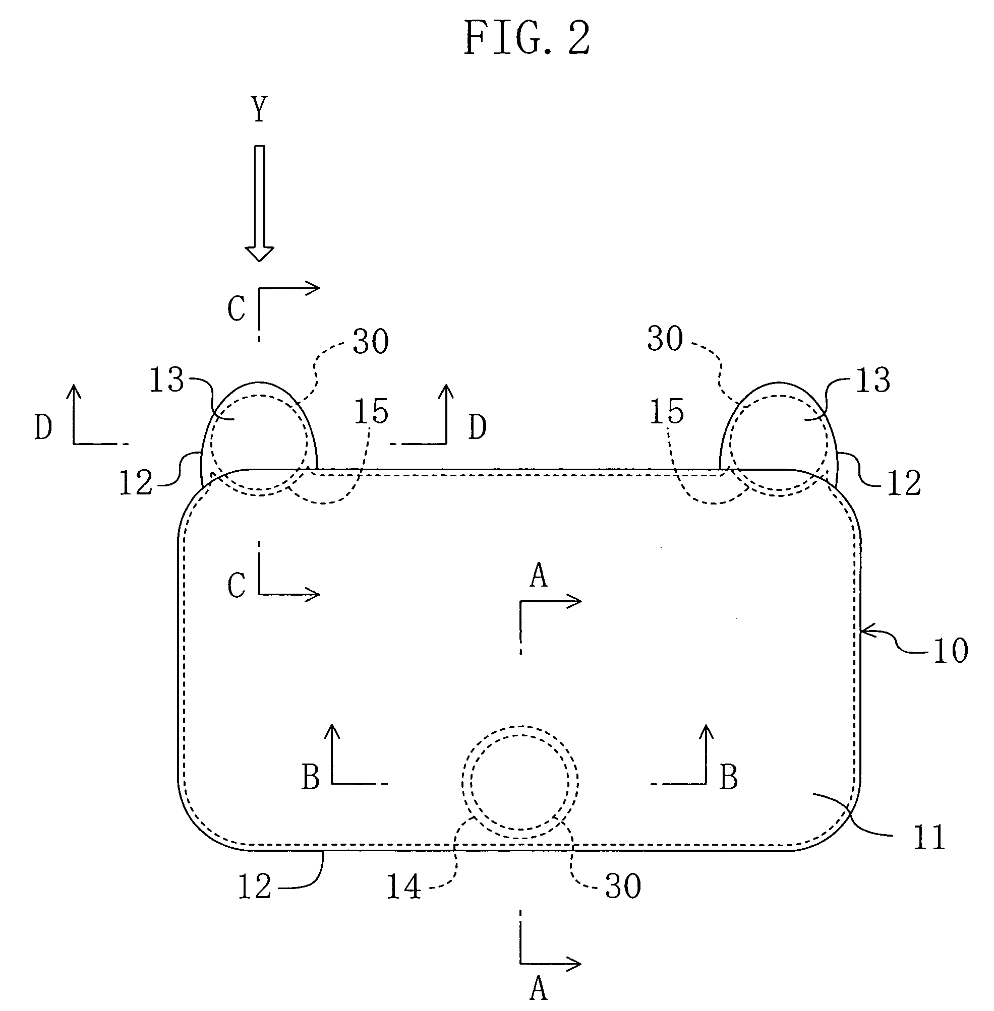
[0042]The engine cover 10 is integrally molded from a resin material. As shown in FIG. 2, the engine cover 10 has a flat plate 11 formed substantially in a rectangle in plan view. As shown in FIG. 3, a downwardly extending peripheral wall 12 is formed at the edges of the flat plate 11. The flat plate 11 has, as also shown in FIG. 2, a pair of extensions 13, 13 extending from both ends of one long edge thereof. Parts of the peripheral wall 12 of ...


PUM


Abstract

A first annular frame is formed on the bottom surface of an engine cover. A mount rubber of columnar shape is inserted into the first annular frame. Projections of the mount rubber are fitted into holes of the first annular frame. A through hole is formed in the mount rubber. An engagement projection is formed on the inner surface of the through hole. An adapter has a small-diameter part formed in the vicinity of the top end and a predetermined distance away from the top end toward the root thereof. The adapter has a flange formed below the smaller-diameter part. The top end part of the adapter is inserted into the through hole of the mount rubber to fit the engagement projection into the small-diameter part and bring the flange into abutment on the bottom surface of the mount rubber.

Description

CROSS-REFERENCES TO RELATED APPLICATIONS[0001]This application claims priority under 35 USC 119 to Japanese Patent Application No. 2004-139440, filed on May 10, 2004, the entire contents of which are incorporated herein by reference.BACKGROUND OF THE INVENTION[0002](a) Field of the Invention[0003]This invention relates to a joint structure between members for joining two members together.[0004](b) Description of the Related Art[0005]As an example of known joint structures for joining two members together, U.S. Pat. No. 6,206,604 (hereinafter, referred to as Patent Document 1) discloses a joint structure between members in which a first member formed to cover a vehicle engine from above is joined to the engine. In the disclosed joint structure, the first member is releasably joined to a second member fixed to the top of the engine and formed in an upwardly extending column. A rubber elastic member is interposed between the first and second members. The elastic member reduces engine v...

Claims


Application Information

Patent Timeline
Patent Type & Authority Patents(United States)
IPC IPC(8): F16C11/06F16D1/00F02F11/00F16B2/04F16B19/10F16B21/07F16F5/00F16F15/08
CPCF16B21/075Y10T403/451Y10T403/455Y10T403/7039Y10T403/14Y10T403/7047Y10T403/4908F16B2200/10
Inventor MIYAHARA, YUTAKAHASHIMOTO, TATSUZOAOKI, RYOUARISAKA, OOMI
Owner PIOLAX CO LTD
Why Eureka
Try Eureka