Brake Carrier

a brake cylinder and brake technology, applied in the field of brake cylinders, can solve the problems of manual labor, inability to automate the installation heavy weight so as to save weight, increase the stability of the connection between the converter unit and the brake cylinder, and keep the cost price of the brake cylinder low

Inactive Publication Date: 2015-02-26
SAF HOLLAND GMBH
View PDF15 Cites 4 Cited by
  • Summary
  • Abstract
  • Description
  • Claims
  • Application Information

AI Technical Summary

Benefits of technology

[0004]According to the invention, the brake carrier of a drum brake which is preferably designed as an expansion wedge drum brake or an expansion wedge drum brake system, respectively, comprises a carrier unit, where the carrier unit has a first connecting section to which a brake cylinder can be fixed, where the carrier unit has a second connecting section to which a converter unit can be fixed, where a housing region is provided between the first and the second connecting section which seats a transmission element and where the brake cylinder, the transmission element and the converter unit can be fixed to an axle element of the utility vehicle. Especially preferably, the carrier unit is a component which takes over the function of a traditional brake carrier. For this purpose, the carrier unit has a first connecting section to which a brake cylinder can be fixed. Especially preferably, the brake cylinder is a pneumatically operated diaphragm brake cylinder and, preferably, is appropriate for large-scale production, ensuring that the cost price of such a brake cylinder can be kept low. In addition, the carrier unit has a second connecting section for fixing a converter unit. Especially preferably, the converter unit is an expansion wedge unit/an expansion wedge drum brake, where a transmission element reaches into, in order to displace to piston elements that move coaxially one to the other. The preferred primary function of the converter unit is the displacement of the brake shoe elements, especially preferably in order to displace them into a position in which they ensure a friction against a brake drum which is pivoted to the axle of the vehicle. According to the inve

Problems solved by technology

As a consequence, the brake carrier is overdesigned and heavier.
Furthermore, the installation

Method used


Image

  • Brake Carrier
  • Brake Carrier
  • Brake Carrier

Examples


Embodiment Construction

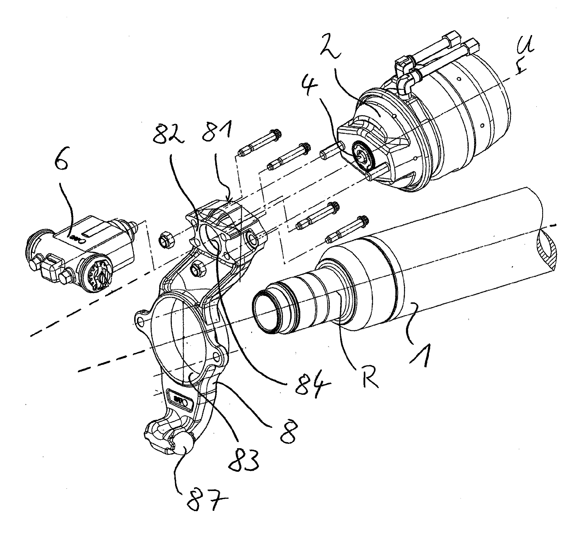
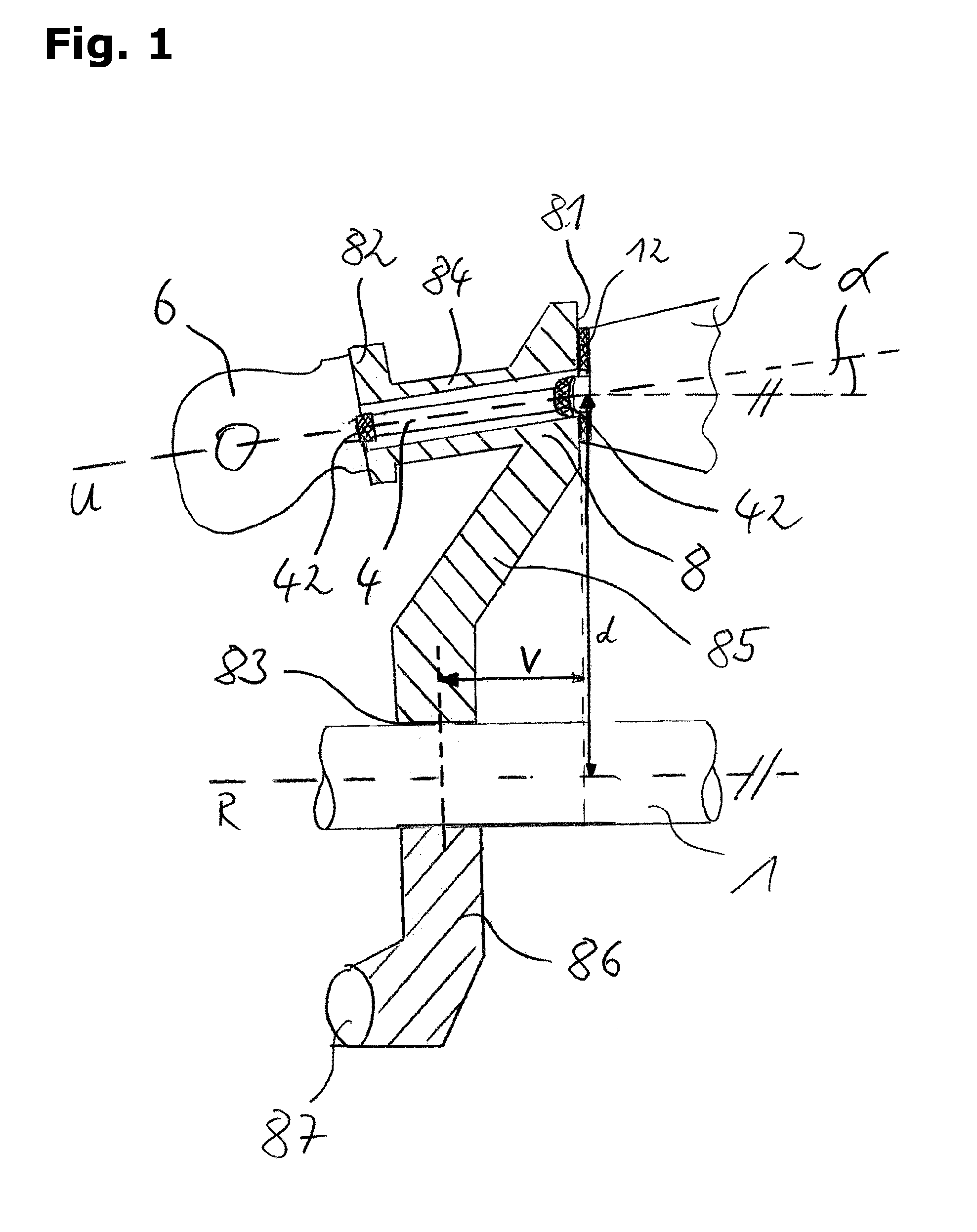
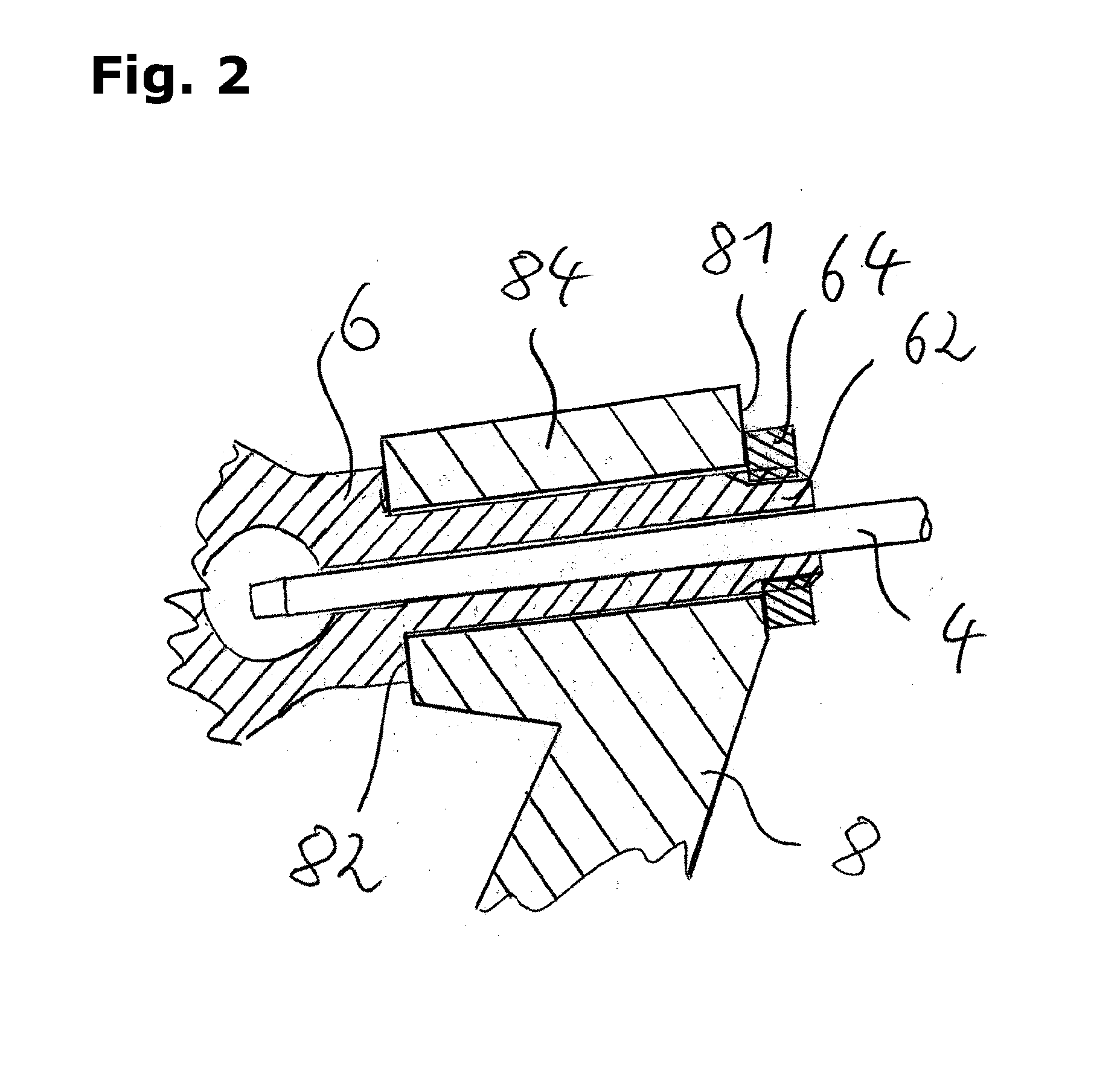
[0026]The brake carrier shown in FIG. 1, preferably an expansion wedge drum brake or an expansion wedge drum brake carrier, respectively, features a carrier unit 8 to which an axle element 1 is fixed at a third connecting section 83. The axle element 1 is preferably a rotationally symmetric, preferably a tube shaped body and especially preferably the rigid axle or an axle stub of a utility vehicle. The third connecting section 83 is, especially preferably, a recess of the carrier unit 8, which is suitable to form a form-fit and force-fit connection to the axle element 1 and, this way, to fix the carrier unit 8 to the axle element 1. Furthermore, the carrier unit 8 has a first connecting section 81, to which a brake cylinder 2 can be fixed to the carrier unit 8. Especially preferably, the brake cylinder 2 is supported via a damping element 12 at a first connecting section 81, where, especially preferably, possible vibrations between the carrier unit 8 and the brake cylinder 2 can be ...


PUM


Abstract

A brake carrier includes a carrier unit having a first connecting section fixed to a brake cylinder, a second connecting section fixed to a converter unit and a third connecting section fixed at an axle element; a transmission element received between the first and second connecting sections; the brake cylinder, the transmission element and the converter unit are fixed to the axle element by the carrier unit; the transmission element can be displaced mainly along an a transmission axle that is tilted in relation to the wheel axle such that the converter unit is aligned closer to the wheel axle than the brake cylinder; the first connecting section is offset along the wheel axle to the connecting section; and the relation of the offset between the first and third connecting sections and the distance to the wheel axle from the transmission axle has values between about 0.1 and about 2.

Description

BACKGROUND OF THE INVENTION[0001]The present invention refers to a brake carrier of a drum brake, in particular, for utility vehicles.[0002]Brake carriers are known from prior art. Preferably, they are used to fix components of the brake system to the axis or the chassis, respectively, of a utility vehicle. Here, the brake carriers known from prior art are, in most cases, designed discoidally and have a number of recesses or bores, respectively, into which mounting elements are inserted for fixing components to the brake carrier. Often, the brake carriers known from prior art are designed to fix different brake systems to the axis of a utility vehicle, where especially preferably, a circular geometry is chosen, which enables to fix brake components of different sizes to the brake carrier. As a consequence, the brake carrier is overdesigned and heavier. Furthermore, the installation of the brake carrier cannot be automated, but has to be carried out manually with great effort. Thus, ...

Claims


Application Information

Patent Timeline
IPC IPC(8): F16D65/00F16D51/00
CPCF16D65/0056F16D2051/003F16D51/00F16D51/20
Inventor DREWES, OLAFCHRIST, ARMIN
Owner SAF HOLLAND GMBH
Why Eureka
Try Eureka