Exhaust adapter, exhaust structure for water heater, and method for installing exhaust adapter

a technology for installing exhaust adapters and water heaters, which is applied in the direction of fluid heaters, manufacturing tools, lighting and heating apparatus, etc., can solve the problems of increasing the installation cost, complex installation, and the inability to make the decision of replacing such a replacement personally, and achieves the effect of convenient and cheap replacemen

Active Publication Date: 2015-02-26
NORITZ CORP
View PDF46 Cites 20 Cited by
  • Summary
  • Abstract
  • Description
  • Claims
  • Application Information

AI Technical Summary

Benefits of technology

[0007]The present invention has been accomplished in view of the aforementioned problems, and it is therefore an object of the present invention to provide an exhaust adapter, an exhaust structure for water heater and a method for installing exhaust adapter, allowing the replacement of the water heater to be performed easily and cheaply without involving changes on the outer appearance of a residential house.

Problems solved by technology

However, such replacement will make the installation complex and increase the installation cost.
In addition, in some regions, the decision of performing such replacement cannot be made personally since the replacement involving changes on the outer appearance of a residential house requires the community approval.
Therefore, in the case where the exhaust gas is to be discharged through an existing exhaust pipe, if the exhaust pipe has a joint point or more, the exhaust gas may leak from the joint point.

Method used


Image

  • Exhaust adapter, exhaust structure for water heater, and method for installing exhaust adapter
  • Exhaust adapter, exhaust structure for water heater, and method for installing exhaust adapter
  • Exhaust adapter, exhaust structure for water heater, and method for installing exhaust adapter

Examples


first embodiment

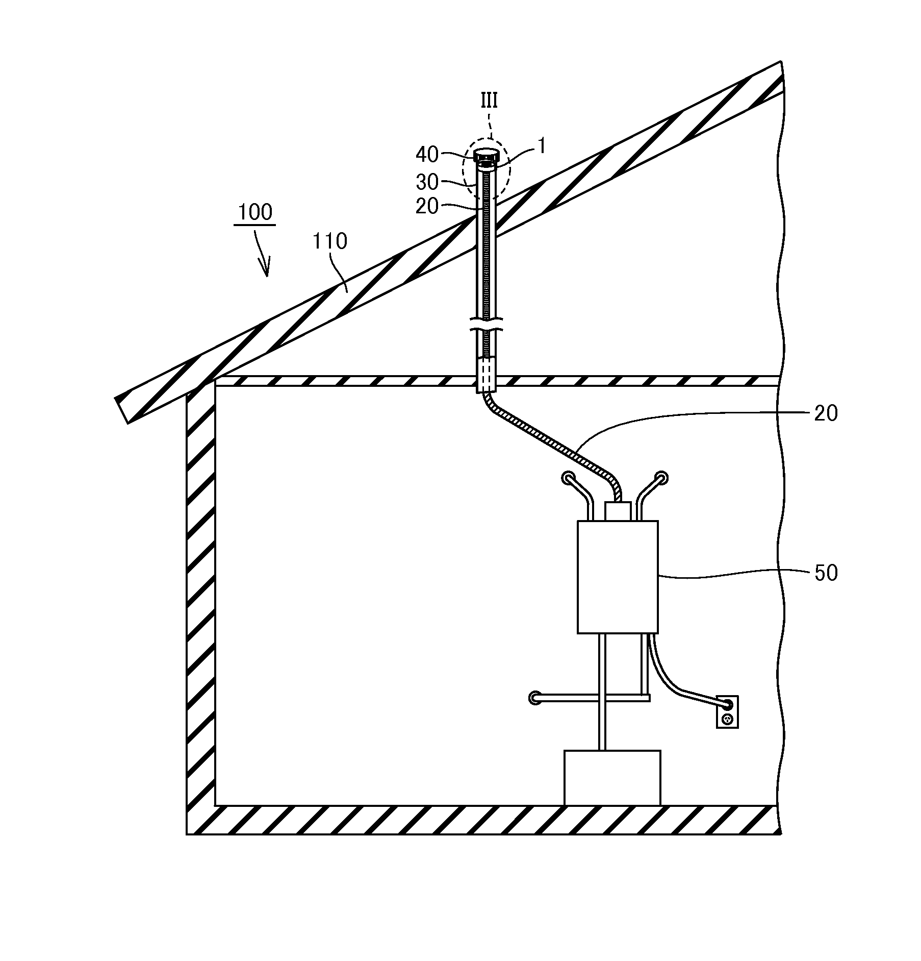
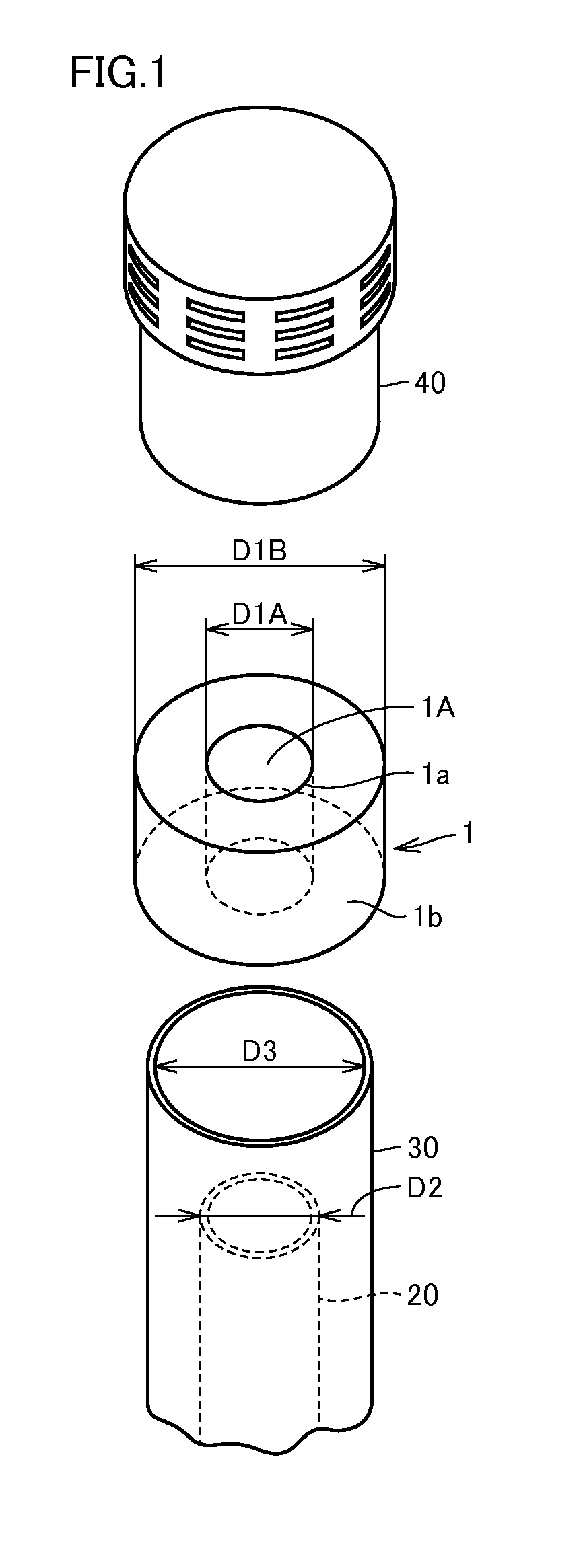
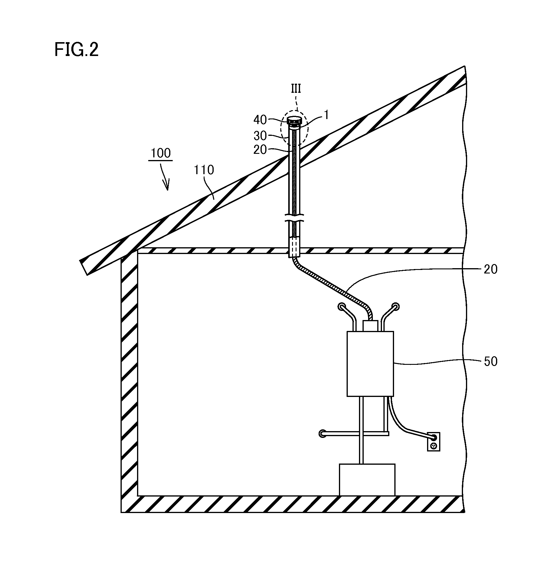
[0100]First, the configurations of an exhaust adapter according to an embodiment of the present invention and an exhaust structure for water heater including the same will be described with reference to FIGS. 1 to 3.

[0101]With reference to FIG. 1, an exhaust adapter 1 according to the present embodiment is configured to fix an exhaust tube (flexible exhaust tube) 20 relative to an exhaust pipe (B vent) 30. Exhaust adapter 1 is formed to have an annular shape enclosing a through hole 1A. Exhaust adapter 1 may be formed into any circular shape (such as a true circle, an enclosed track shape or an ellipse), any annular shape with multiple sides or any other annular shape, as long as the shape of an inner peripheral surface of exhaust adapter 1 matches the shape of an outer peripheral surface of exhaust tube 20 and the shape of an outer peripheral surface thereof matches the shape of an inner peripheral surface of exhaust pipe 30.

[0102]In exhaust adapter 1, at least an inner peripheral ...

second embodiment

[0179]With reference to FIGS. 27 and 28, exhaust adapter 1 of the present embodiment is formed to have an annular shape enclosing through hole 1A, and is configured to be supported by exhaust pipe 30 at the outer peripheral side of the annular shape and to support exhaust tube 20 at the inner peripheral side. Exhaust adapter 1 includes an annular member 1c, an annular outer peripheral projection member 1d, an abutting projection member 1e and an annular inner peripheral projection member 1f.

[0180]Annular member 1c includes one end surface 1U and the other end surface 1L facing each other and includes through hole 1A penetrating across one end surface 1U and the other end surface 1L. Annular member 1c includes a main part 1ca and an extension part 1cb. Main part 1ca and extension part 1cb each are formed to have an annular shape and the two are joined to each other. The end surface opposite to the portion where extension part 1cb is jointed to main part 1ca serves as one end surface...

third embodiment

[0220]With reference to FIGS. 39 and 40, exhaust adapter 1 of the present embodiment includes annular member 1c, annular outer peripheral projection member 1d and annular inner peripheral projection member 1f.

[0221]Annular member 1c includes one end surface 1U and the other end surface 1L facing each other and includes through hole 1A penetrating across one end surface 1U and the other end surface 1L. Annular outer peripheral projection member 1d projects all around from outer peripheral surface 1b of annular member 1c outward circumferentially. Outer peripheral projection member 1d may include a plurality of annular projections 1da projecting from outer peripheral surface 1b of annular member 1c outward circumferentially. In the present embodiment, outer peripheral projection member 1d is composed of, for example, two projections 1da.

[0222]Outer peripheral projection member 1d (each of the plurality of projections 1da) is configured to have a width decreasing as it extends toward...


PUM

PropertyMeasurementUnit
temperatureaaaaaaaaaa
annular shapeaaaaaaaaaa
widthaaaaaaaaaa

Abstract

An exhaust adapter secures an exhaust tube relative to an exhaust pipe. The exhaust adapter is formed to have an annular shape enclosing a through hole, and is mounted on the outer peripheral surface of the exhaust tube and on the inner peripheral surface of the exhaust pipe by inserting the exhaust tube into the through hole. When the exhaust adapter is being fitted on the outer peripheral surface of the exhaust tube, the inner peripheral surface of the exhaust adapter presses the outer peripheral surface of the exhaust tube, and when the exhaust adapter is being fitted on the inner peripheral surface of the exhaust pipe, the outer peripheral surface of the exhaust adapter presses the inner peripheral surface of the exhaust pipe.

Description

BACKGROUND OF THE INVENTION[0001]1. Field of the Invention[0002]The present invention relates to an exhaust adapter, an exhaust structure for water heater, and a method for installing exhaust adapter.[0003]2. Description of the Background Art[0004]Nowadays, among water heaters being sold in the United States market, a tank water heater is popular. Generally, the tank water heater is installed, for example, inside a boiler room. The exhaust gas generated from combustion in the tank water heater is generally discharged outside the roof of a residential house through an exhaust pipe. Upon replacing the tank water heater with an instantaneous water heater, all of the installed exhaust members, including for example the exhaust pipe which has been installed, in the residential house will also be replaced.[0005]However, such replacement will make the installation complex and increase the installation cost. In addition, in some regions, the decision of performing such replacement cannot be...

Claims


Application Information

Patent Timeline
Patent Type & Authority Applications(United States)
IPC IPC(8): F23J13/04F23J13/02F24H9/18F16L7/00F24H9/12
CPCF23J13/04F16L7/00F23J2211/40F24H9/1836F23J13/02F24H9/122F16L7/02F23L17/04F23J2211/101F23J2213/202F23J2213/204F23J2213/50F23J2900/13005F24H9/16F24H8/00Y10T29/49826Y02B30/00
Inventor NAGANO, TAKANORISHIMOMURA, KOJI
Owner NORITZ CORP
Why Eureka
Try Eureka