
Method for receiving downlink control signal, user equipment, method for transmitting downlink control signal and base station

a control signal and control signal technology, applied in the field of wireless communication systems, can solve the problems of signal not being correctly demodulated or decoded, signal not being successful in reaching the receiving device, etc., and achieve the effect of improving the range of a signal transmitted by a transmitting device capable of being reached with valid strength or more, and improving the reliability of a signal transmitted by a transmitting devi

Active Publication Date: 2015-03-05
LG ELECTRONICS INC
View PDF2 Cites 88 Cited by
  • Summary
  • Abstract
  • Description
  • Claims
  • Application Information

AI Technical Summary

Benefits of technology

The present invention improves the range and reliability of signals transmitted by a transmitting device. This means that the device can send signals to a larger area and with greater strength. It also ensures that the signals are accurate and can be trusted. Overall, the invention enhances the efficiency and effectiveness of signal transmission.

Problems solved by technology

If signal quality is deteriorated due to occurrence of an obstacle to the radio channel formed between the transmitting device and a receiving device which is a destination of the signal, the signal may not successfully reach the receiving device or, even if the signal reaches the receiving device, the signal may not be correctly demodulated or decoded due to errors.

Method used


Image

  • Method for receiving downlink control signal, user equipment, method for transmitting downlink control signal and base station
  • Method for receiving downlink control signal, user equipment, method for transmitting downlink control signal and base station
  • Method for receiving downlink control signal, user equipment, method for transmitting downlink control signal and base station

Examples


first embodiment

[0029]FIG. 13 is a diagram for explaining a first embodiment according to the present invention.

second embodiment

[0030]FIG. 14 is a diagram for explaining a second embodiment according to the present invention.

third embodiment

[0031]FIGS. 15, 16, and 17 are diagrams for explaining a third embodiment according to the present invention.

[0032]FIG. 18 is a block diagram illustrating elements of a transmitting device 10 and a receiving device 20 for implementing the present invention.

MODE FOR INVENTION

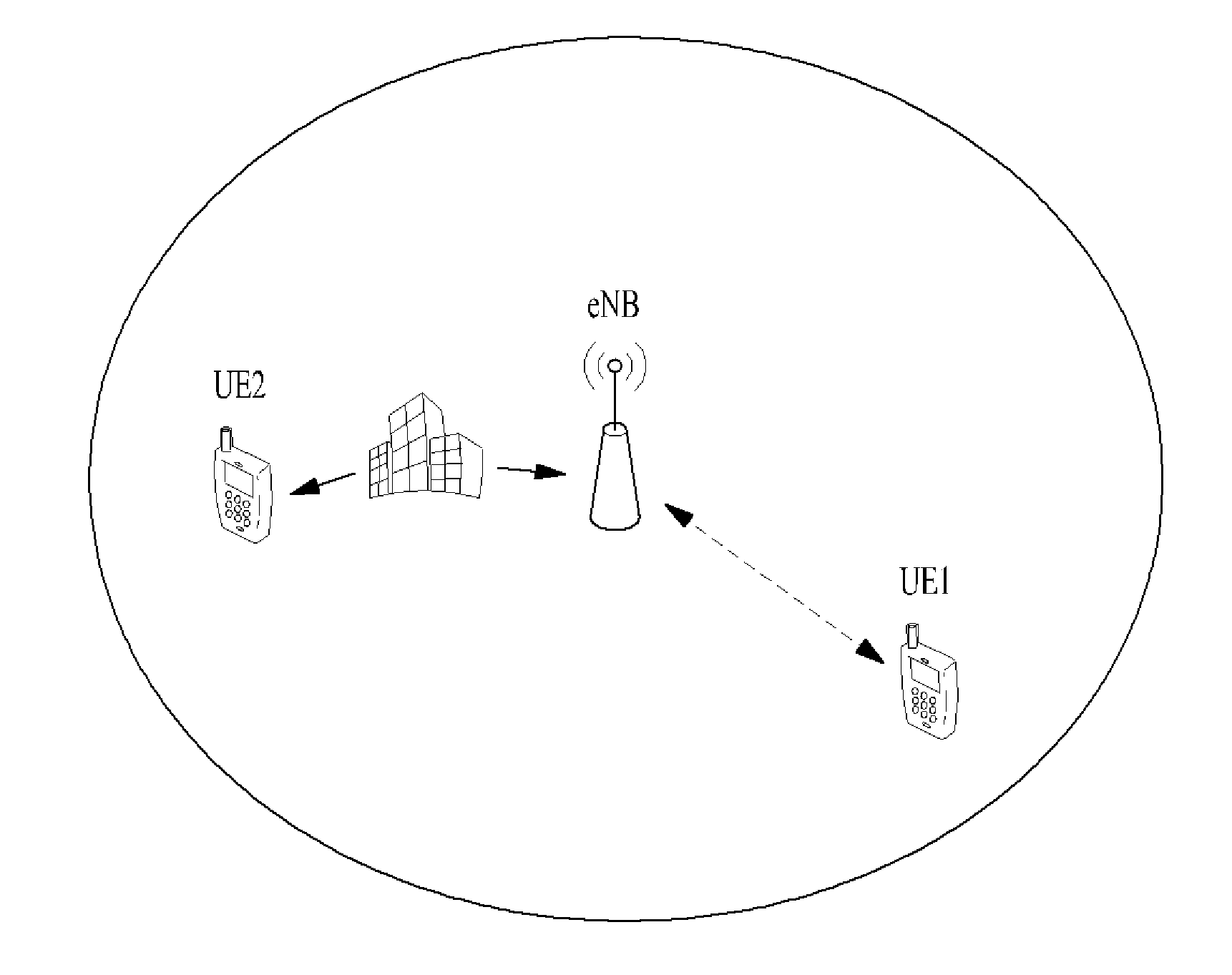
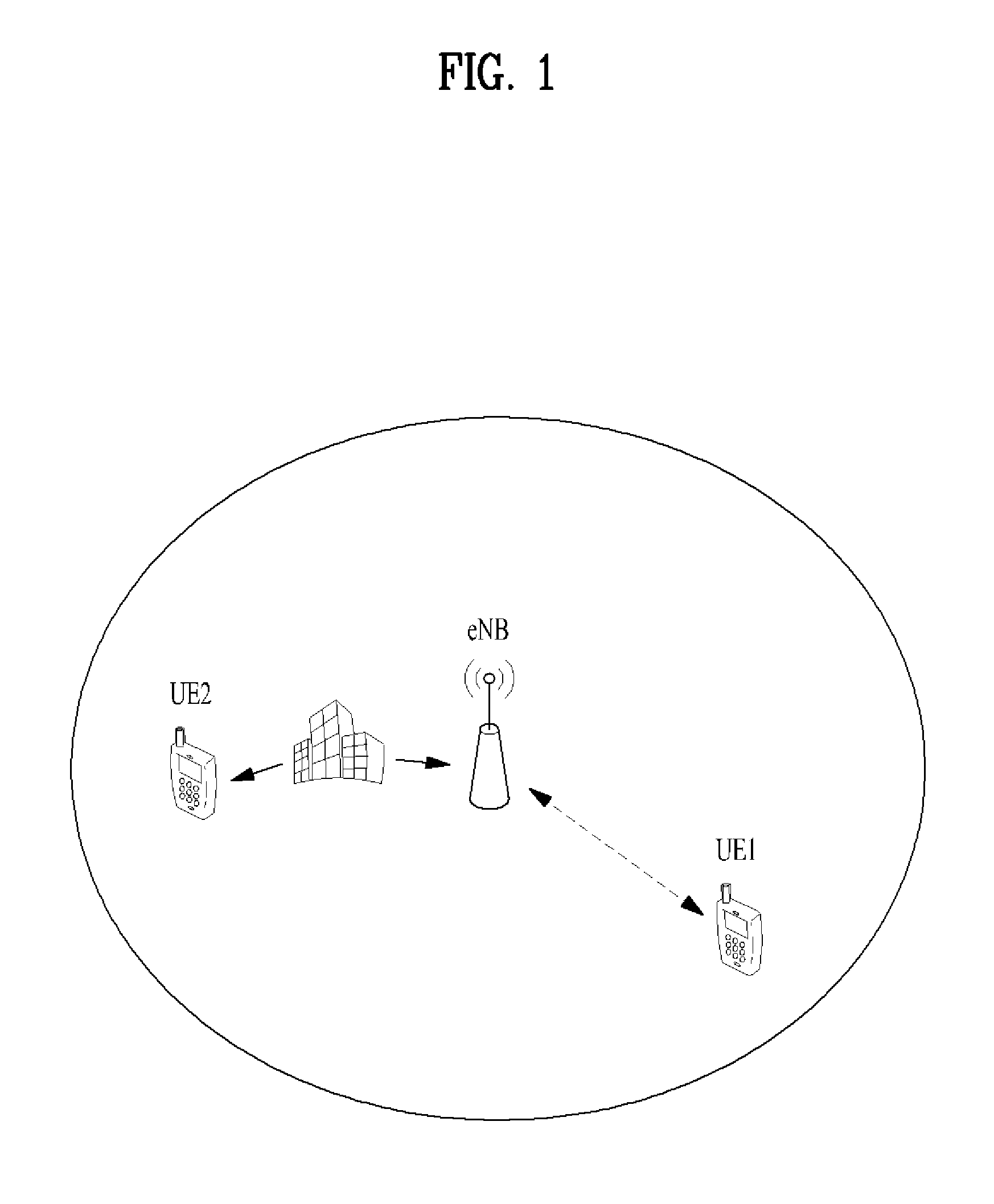
[0033]The present invention proposes that a format of an uplink / downlink signal be modified in order to improve coverage within which a signal transmitted by a transmitting device can be effectively reached. Referring to FIG. 1, the reliability of transmission data is more important than the amount of transmission data in a situation in which UE reception performance of a signal transmitted from an eNB to a UE such as UE2, or eNB reception performance of a signal transmitted from a UE such as UE1 to the eNB may be deteriorated. Accordingly, the present invention proposes raising importance of a control signal with respect to the transmission data instead of restricting data rate.

[0034]Reference will now be made i...


PUM


Abstract

In the event where a channel strength between UE and eNB is weakened, the eNB of the present invention may configure downlink control information into the format in which at least one of fields of pre-defined existing format is deleted, the length of a relevant field is shortened to be shorter than a pre-defined length of the relevant field, or an error correcting code is added by the amount of the length deleted or reduced. UE decodes a downlink signal according to the modified format to acquire downlink control information of its own.

Description

TECHNICAL FIELD[0001]The present invention relates to a wireless communication system. Specifically, the present invention relates to a method and apparatus for transmitting / receiving an uplink control signal.BACKGROUND ART[0002]In a wireless communication system, a transmitting device transmits a signal through a radio frequency channel. If signal quality is deteriorated due to occurrence of an obstacle to the radio channel formed between the transmitting device and a receiving device which is a destination of the signal, the signal may not successfully reach the receiving device or, even if the signal reaches the receiving device, the signal may not be correctly demodulated or decoded due to errors.[0003]FIG. 1 is a diagram for explaining an example of low reception signal strength. Particularly, FIG. 1 illustrates an example of increasing pathloss between an evolved NodeB (eNB) and a user equipment (UE). When a UE, UE1 for example, is located at a cell edge of a geographic region...

Claims


Application Information

Patent Timeline
IPC IPC(8): H04W72/04
CPCH04W72/042H04L1/0031H04L1/1896H04L5/0016H04L5/0023H04L5/0044H04L5/0048H04L5/0053H04L5/1469H04W72/23
Inventor SEO, DAEWONKIM, HAKSEONGSEO, HANBYUL
Owner LG ELECTRONICS INC
Learn More