Denture Reference and Registration System

a denture and bar support technology, applied in dental surgery, fastening prosthesis, medical science, etc., can solve the problems of difficult to precisely and securely fit in the denture, no plaster model having implant analogues is available to align and position the bar, and the bar is often complex in shape, so as to achieve the effect of convenient removal

Active Publication Date: 2015-03-05
GLOBAL DENTAL SCI
View PDF9 Cites 30 Cited by
  • Summary
  • Abstract
  • Description
  • Claims
  • Application Information

AI Technical Summary

Benefits of technology

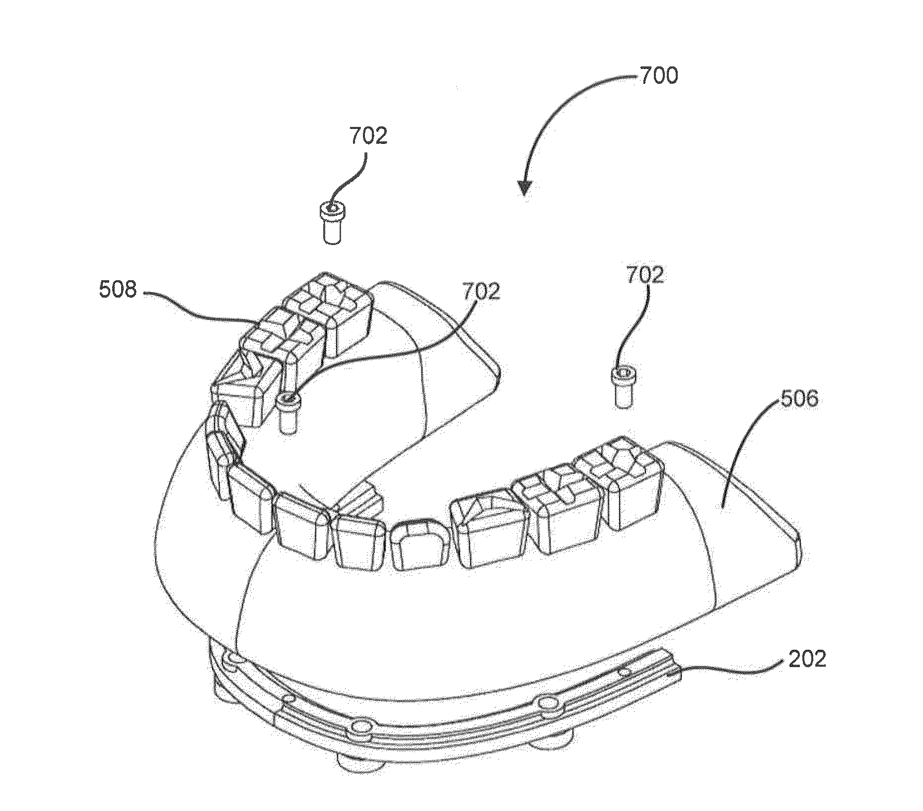
[0010]In accordance with another exemplary embodiment, an improved support bar is accurately referenced and registered with respect to an improved denture base, yet is also readily removable, for example, by snap-fitting the base onto the bar.

Problems solved by technology

With CAD / CAM technology, the denture is made directly without using wax and plaster models, thus no plaster model having implant analogues is available to align and position the bar.
However, the bar is often complex in shape and difficult to precisely and securely fit in the denture.
Furthermore, even if such a plaster model were made to assist with aligning and positioning the bar in the cavity, the fitting of the denture onto the bar is difficult and often imprecise because it is difficult to preserve the proper registration of the bar with respect to the denture while they are mated and the bar disconnected from the plaster model, particularly if the model impedes access to the cavity in the denture.
Moreover, the production of such a model introduces unwanted delay and expense.

Method used


Image

  • Denture Reference and Registration System
  • Denture Reference and Registration System
  • Denture Reference and Registration System

Examples


Embodiment Construction

[0026]The following description is of various exemplary embodiments only, and is not intended to limit the scope, applicability or configuration of the present disclosure in any way. Rather, the following description is intended to provide a convenient illustration for implementing various embodiments including the best mode. As will become apparent, various changes may be made in the function and arrangement of the elements described in these embodiments without departing from the scope of the appended claims.

[0027]For the sake of brevity, conventional techniques for manufacturing and construction may not be described in detail herein. Furthermore, the connecting lines shown in various figures contained herein are intended to represent exemplary functional relationships and / or physical couplings between various elements. It should be noted that many alternative or additional functional relationships or physical connections may be present in a practical method of construction.

[0028]...


PUM


Abstract

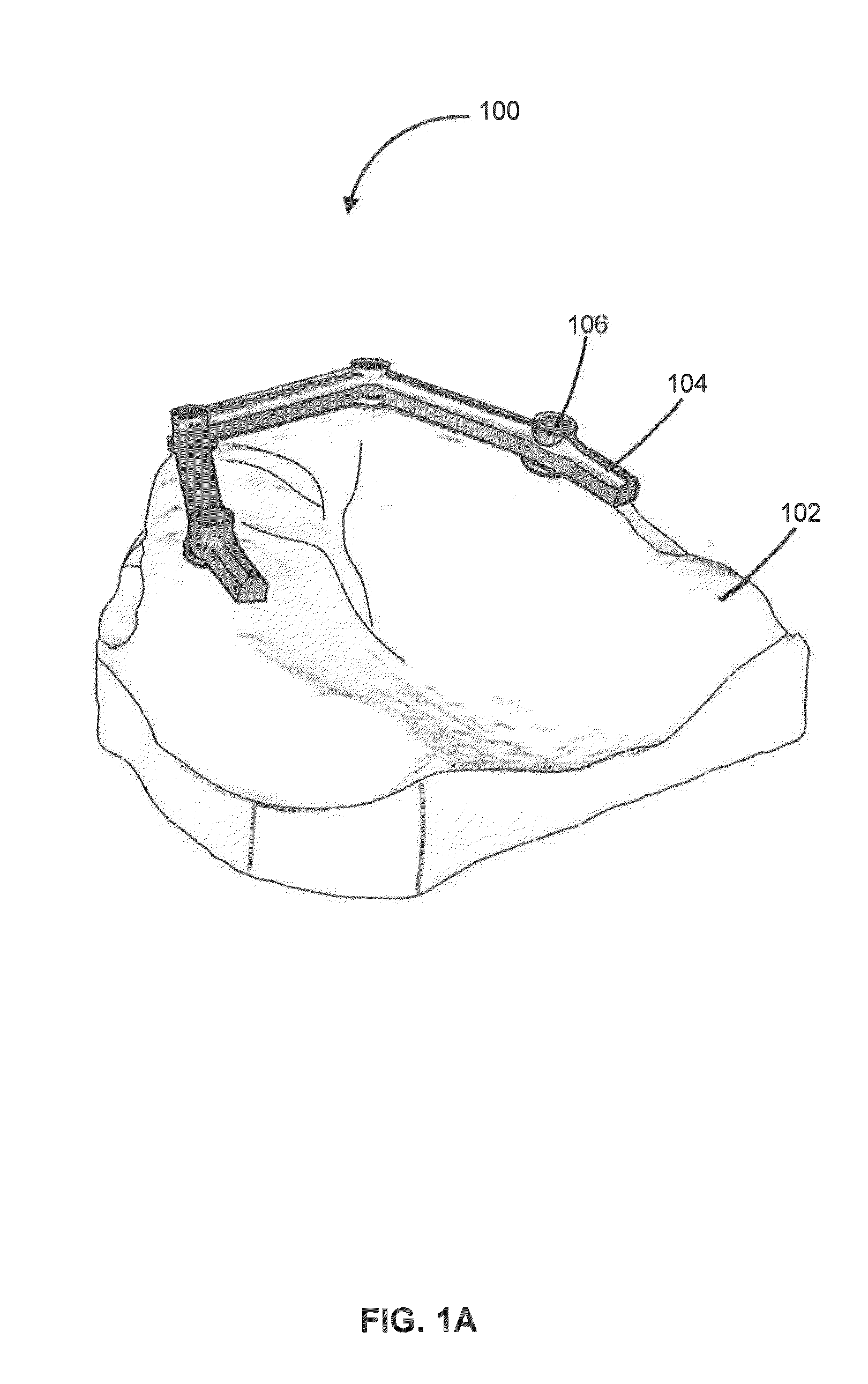
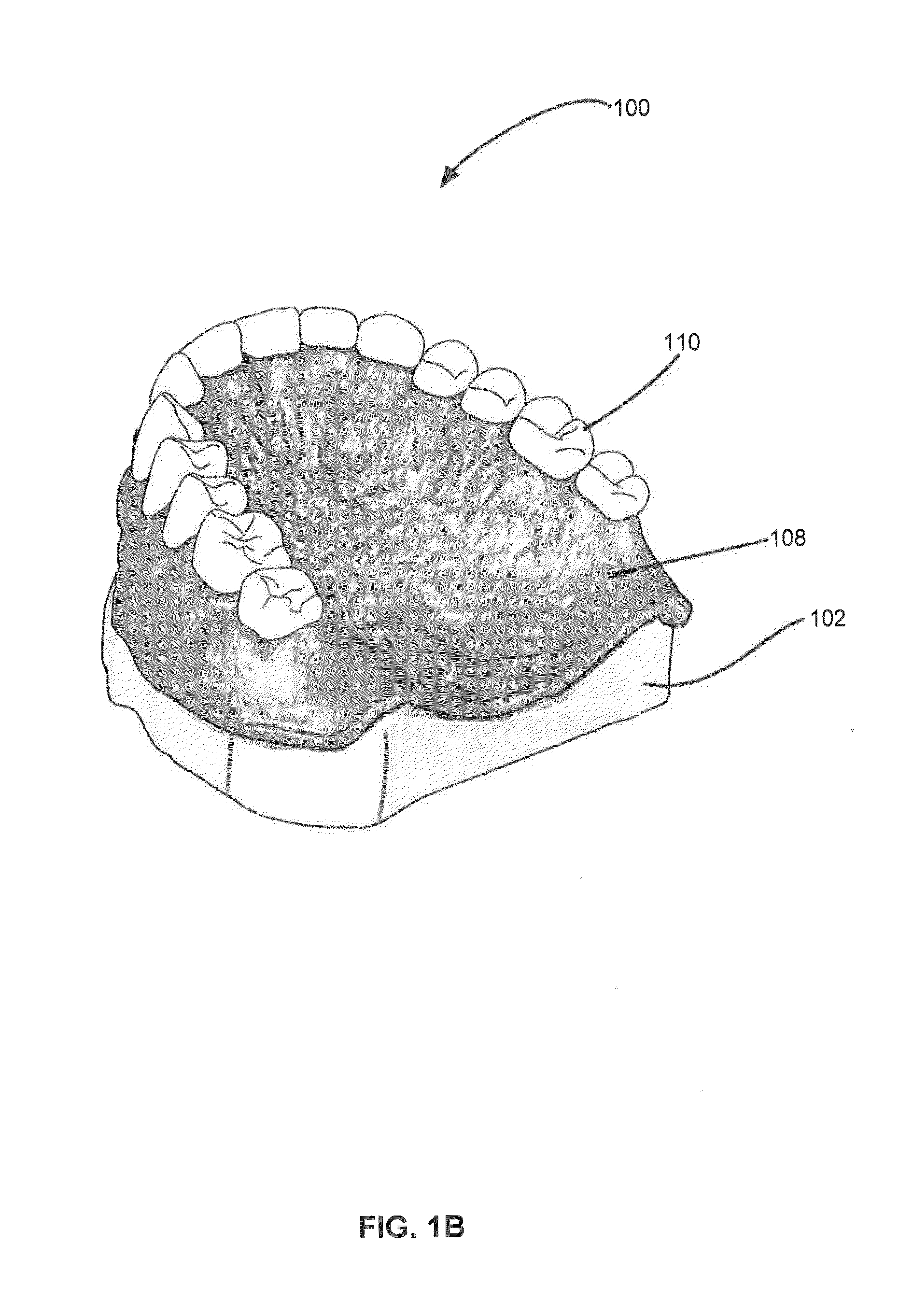
An improved denture system is disclosed. An improved denture system has a support bar and an artificial denture base. The denture base has an oversize cutout and a corresponding cavity and the support bar has a plurality of reference posts which mechanically interface with the corresponding cavity so that the support bar is connected to the artificial denture base and provides reinforcement and stability to the denture system. The shape and position of the reference posts fully constrains the support bar in a fixed position with reference to the denture base. In one embodiment, the denture base snap-fits onto the support bar.

Description

FIELD OF INVENTION[0001]The present invention relates to implant and bar-supported or bar-retained dentures. More particularly, the present invention relates to a bar reference and registration system to place a bar in a CAD / CAM manufactured denture.BACKGROUND OF THE INVENTION[0002]In the field of dentures a metal bar on implants is used to stabilize the denture in the mouth and to strengthen the denture structure to avoid breakage.[0003]In the traditional denture manufacturing process an impression is made of a patient's implants and edentulous or partially edentulous ridges. The impression is used to construct a plaster model of the patient's edentulous ridges and implants. A metal bar is manufactured to fit exactly on the plaster model, and to align with the patient's implants according to the implant analogs in the plaster model. The metal bar is installed on the plaster model and the denture structure is then built around the bar in wax. Artificial teeth are placed in the wax r...

Claims


Application Information

Patent Timeline
Patent Type & Authority Applications(United States)
IPC IPC(8): A61C13/265A61C8/00
CPCA61C8/0048A61C13/2656A61C8/0068A61C8/0095
Inventor GROBBEE, JOHANNES PETRUS MICHAELGAUBERT, JERRY
Owner GLOBAL DENTAL SCI
Why Eureka
Try Eureka